
Audio Noise Filter circuit

The audio noise filter circuit is essential in applications where clarity and quality of sound are paramount. By employing a low-pass filter, the circuit allows audio signals below a specified cutoff frequency to pass through while attenuating higher frequency noise. Conversely, the high-pass filter permits signals above a certain cutoff frequency to pass, thereby rejecting lower frequency interference. The cascade configuration enhances the overall filtering effect, ensuring that only the desired audio frequencies are transmitted.
In practical implementations, the low-pass filter can be designed using passive components such as resistors and capacitors or active components like operational amplifiers for better performance. The cutoff frequency of the low-pass filter is determined by the values of these components, allowing for customization based on the specific application requirements. Similarly, the high-pass filter is constructed using a complementary set of components, where the cutoff frequency is also adjustable.
The integration of both filters into a single circuit enables the creation of a robust audio processing unit that can be utilized in various devices, including audio mixers, amplifiers, and sound reinforcement systems. This configuration not only enhances sound quality but also minimizes the impact of external noise sources, resulting in a cleaner audio output. The design considerations for this circuit include component selection, frequency response, and impedance matching to ensure optimal performance across the intended audio frequency spectrum.This audio noise filter circuit is a bandpass filter for audio frequency band. It filters unwanted signals that are lower or higher than the audio frequencies. It has 2 filters: a low pass filter and a high pass filter in a cascade configur.. 🔗 External reference
Related Circuits
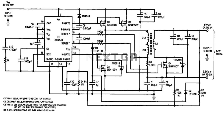
One LTC 1149 synchronous switching regulator can deliver both 3.3 and 5 V outputs. The design's simplicity, low cost, and high efficiency make it a strong contender for portable, battery-powered applications. The circuit described accepts input voltages from 8...
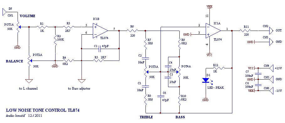
A tone control or pre-amplifier is an amplifier circuit that enhances audio signals. It is important to understand the characteristics, advantages, and disadvantages of various amplifier equipment, as the performance of different amplifiers may not show significant differences. The...
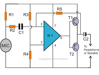
This document discusses the creation of an electronic spy bug circuit using two methods: one involving a wired connection from the transmitter to the receiver, and the other being a completely wireless setup capable of eavesdropping on conversations up...
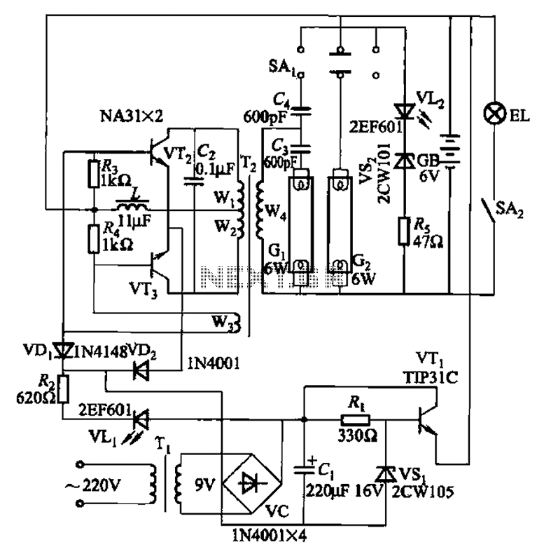
This is a Nissan Panasonic rechargeable emergency fluorescent lamp circuit. It features built-in 6V, 4Ah high-energy batteries that can be directly charged. The circuit supports two 6W fluorescent lamps. It includes functional switches SAi and SAz. When SAi is...
The two T-notch filter can be utilized to block unwanted frequencies or, when incorporated into an operational amplifier, function as a bandpass filter. The notch frequency occurs when the capacitive reactance equals the resistance (Xc = R), and if...
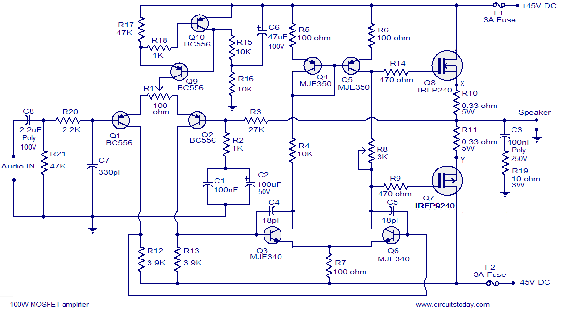
Hi-fi 100W MOSFET power amplifier circuit. Operates from a 45V dual supply. Delivers 100W to an 8-ohm speaker and 160W to a 4-ohm speaker, with low distortion. The Hi-fi 100W MOSFET power amplifier circuit is designed to provide high-quality audio...