
Twin-T RC Notch Filter

The T-notch filter is a specialized circuit designed to attenuate specific unwanted frequencies while allowing others to pass. Its operation is based on the principle of resonance, where the notch frequency is determined by the relationship between resistance (R) and capacitive reactance (Xc). In practical applications, this filter can be integrated into audio processing systems to enhance sound quality by selectively boosting bass and treble frequencies while reducing midrange interference.
In designing the circuit, the choice of component values is crucial. For instance, employing 1.5K ohm resistors in conjunction with 0.1 µF capacitors establishes a frequency response that effectively creates a -10 dB attenuation band between 500 Hz and 2 kHz. This configuration allows for precise control over the audio signal, enabling users to tailor the output to their preferences.
Furthermore, when implementing this filter in an operational amplifier configuration as a bandpass filter, careful consideration must be given to the feedback and gain settings to prevent oscillation. This may involve adjusting component values or incorporating additional resistive elements to stabilize the circuit's response.
Overall, the T-notch filter is an invaluable tool in audio engineering, providing flexibility in frequency response and enhancing the listening experience through effective frequency management.The two T-notch filter can be used to block unwanted frequencies or if placed in an op amp as a bandpass filter. the notch frequency occurs where the capacitive reactance equals the resistance (Xc = R) and if the values are close, the attenuation can be very high and the notch frequency virtually eliminated, Insertion of the filter depends on the l
oad, the output is connected to the subject so that the resistors must be of much lower value than the load for minimal loss. For audio frequencies, the filter may act as a bass and treble boost circuit by attenuating the midrange.
With 1. 5K resistors and capacitors 0. 1 uF, the band is in stop-10dB 500 Hz to 2 kHz. The depth and breadth of the reaction can be slightly adjusted to a value of 0. 5 R and adding some resistance at the C-values, If the circuit is an operational amplifier is used as a bandpass filter, the response should be reduced to avoid oscillation. Be the first of your friends to get free diy electronics projects, circuits diagrams, hacks, mods, gadgets & gizmo automatically each time we publish.
Your email address & privacy are safe with us ! 🔗 External reference
Related Circuits
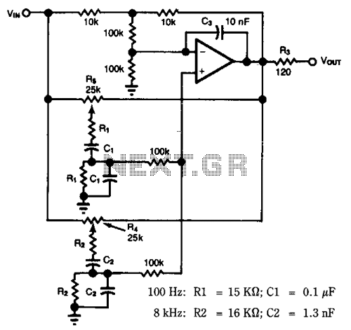
Most audio tone controls affect midband gain and often create booming or hissing sounds when activated. These problems can be avoided by using a dual Wien-bridge filter to provide independent control of the treble and bass frequencies. Experiments with...
A Butterworth filter is a type of filter characterized by a frequency response that is flat within the passband region. This filter was first described by British engineer Stephen Butterworth. A Butterworth filter is designed to provide a maximally flat...
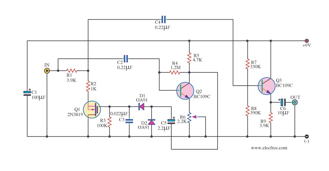
In audio systems, noise signals are generally undesirable, and efforts are often made to eliminate them. Transistors can be utilized effectively for this purpose due to their availability and low noise characteristics. The following circuit serves as a Noise...
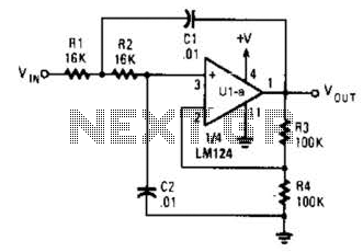
The circuit presented has a cutoff frequency of approximately 1 kHz. The resistors R1, R2, and capacitors C1, C2 can be adjusted to achieve any desired frequency. The circuit is designed as a filter, likely a low-pass or high-pass filter,...
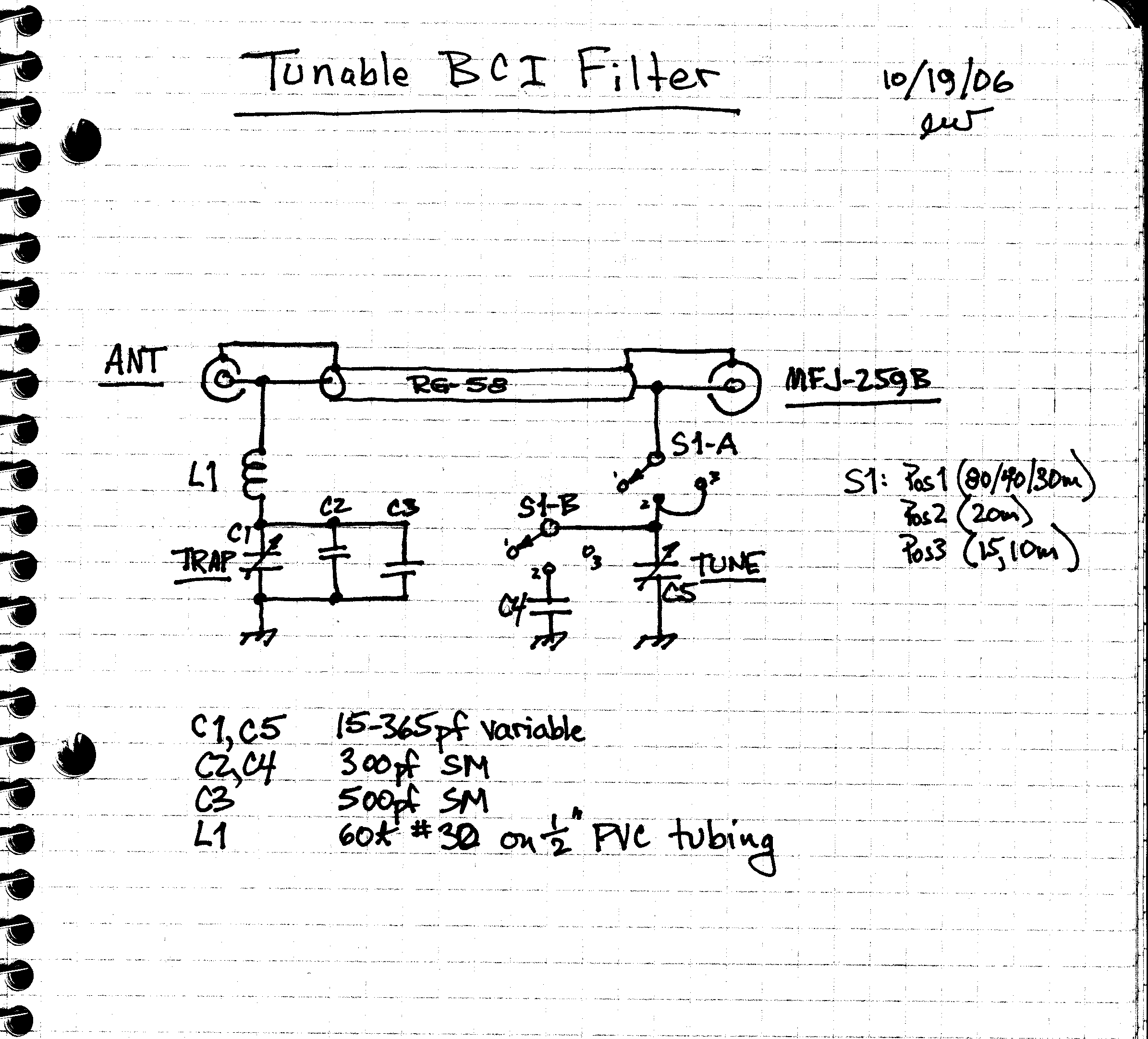
The design involves creating an AM broadcast signal eliminator. An undesired AM broadcast signal is directed to ground using a series resonant circuit composed of inductor L1 and capacitors C1, C2, and C3. At high frequencies, this series circuit...
Replacing the LC modulation circuit with an active filter allows for the elimination of large and costly inductance coils in frequency shift key control demodulators. This approach not only reduces the size of the circuit but also enhances the...