
Simple Audio Filter Analyzer Circuit

The described circuit facilitates the visualization of a filter's frequency response using an oscilloscope. This setup employs a combination of voltage-controlled oscillators (VCOs) and operational amplifiers to generate and optimize the signals used for the frequency sweep. The primary component, the 566 VCO (U1), is responsible for producing a very low frequency (VLF) triangle wave that modulates the frequency of the subsequent stage. This triangle wave serves as a basis for the frequency sweep across the filter.
Operational amplifier U2, a 741 type, plays a crucial role in optimizing the output amplitude and ensuring the correct DC component is maintained. This optimization is essential for accurate frequency response analysis. The second VCO (U3) generates the sweeping triangle wave, with its frequency adjustable via switch S1, allowing for flexible testing across various frequency ranges.
Operational amplifier U4 is configured as a bandpass filter, demonstrating the filtering characteristics of the circuit. The inclusion of diode D1 is critical as it clips the lower half of the output signal, producing a bell-shaped curve that is easier to analyze on the oscilloscope.
To properly set up the oscilloscope for this analysis, specific configurations must be made. The TIME/CM setting determines the time scale of the displayed waveform, while the VOLTS/CM setting adjusts the vertical scale to ensure the signal is adequately displayed. The external trigger input facilitates synchronization with the start of the frequency sweep, allowing the oscilloscope to accurately capture the response curve.
During operation, the adjustment of the triggering level is vital to ensure that the displayed sweep accurately represents the low-to-high frequency transition. This careful calibration allows for a clear visualization of the filter's frequency response, showcasing how the output varies as the input frequency approaches, reaches, and surpasses the bandpass range. The final connection to the filter output past the diode allows for the observation of the filtered response on the oscilloscope, providing valuable insights into the circuit's performance characteristics.When this circuit is connected to a filter and an oscilloscope, the scope displays the filter`s frequency response. A frequency that sweeps from low to high is applied to a filter. An oscilloscope is triggered by* the start of the sweep and ends its trace at the highest frequency of the sweep.
The filter output goes to the vertical amplifier of th e oscilloscope. Using bandpass filters as an example, as the bandpass frequency is approached, reached, and passed, the scope follows the peaking output and draws the response curve. A neat effect! The 566 VCO (Ul) produces a VLF triangle wave to frequency modulate the next stage. It also produces a square wave to externally trigger the scope. Op amp U2 (a 741 unit) optimizes the amplitude and the dc component. Another VCO (U3) produces the actual sweeping triangle wave. Its frequency is selectable via SI. Op amp U4 (another 741 op amp) is set up as a bandpass filter and has been included as an example filter.
Finally, diode D1 chops off the bottom half of the output, and leaves a nice bell curve. lb set up and operate, power-up the circuit and scope. Set the scope`s TIME/CM to 50 ms/cm. Set the VOLTS/CM control to 2 V. Attach a probe from the circuit`s trigger to the scope`s external trigger input. Set the triggering mode to normal, external. Attach a probe from the vertical amplifier to TP1. You`ll see a diagonal line that runs across the CRT. Input coupling should be set to dc. Adjust the triggering level until the diagonal runs from the upper left to the lower right of the CRT to ensure a displayed sweep from low to high. Now, disconnect the probe from TP1 and attach it to the filter output past the diode. 🔗 External reference
Related Circuits
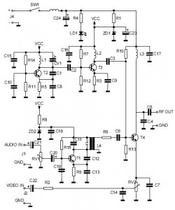
This is the circuit diagram of an audio/video modulator. The circuit converts audio and video signals into a UHF TV signal, allowing a video signal from a camera or other source to be connected to a standard TV set....
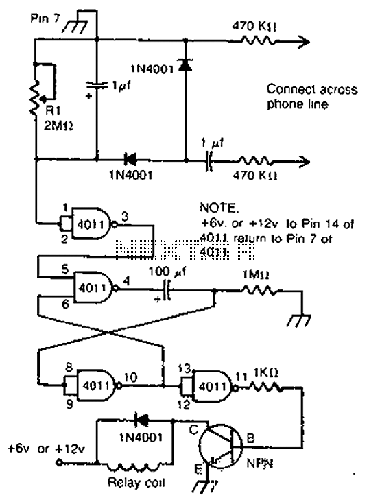
By cross-connecting the telephone ringing circuit, when the phone rings, the circuit activates the relay. It utilizes a delay in contact to drive various devices such as bells, sirens, buzzers, or lights. The telephone ringing circuit is designed to detect...
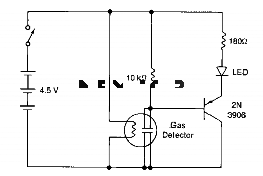
The circuit illustrates a basic yes/no gas detector. It utilizes three 1.5-V D cells as the power source, with SI functioning as an on/off switch. The heater is powered directly from the battery, while the electrodes are connected in...
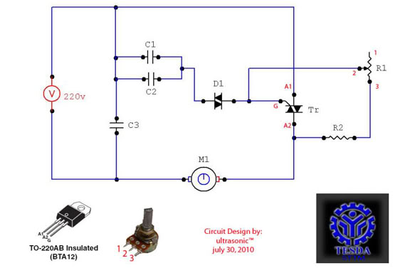
This circuit functions as a motor controller, allowing for easy control and variation of the RPM and phase of an AC motor. The power source is directly 220VAC, and it can handle a load of approximately 1 horsepower AC...
Arcing completes a circuit -- closes a system -- between two voltage potentials. When arcing occurs, two oppositely charged static voltage potentials can cancel each other out. The arcing problems that occur are usually between two electrically isolated voltage...
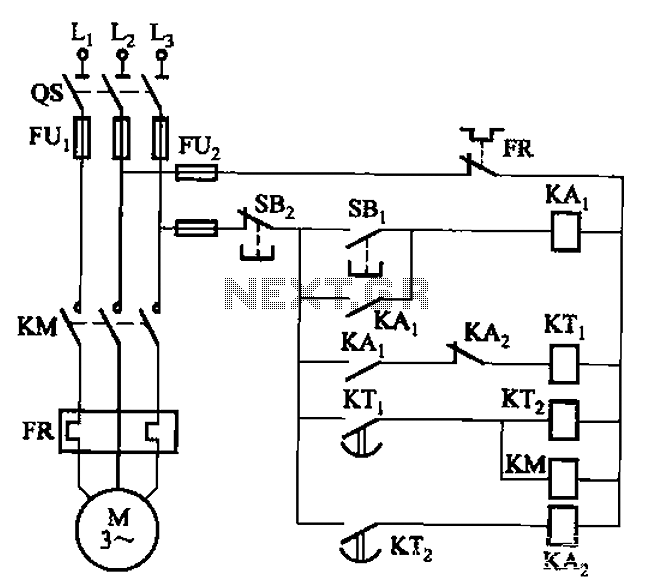
The circuit illustrated in Figure 3-76 employs two time relays, KTi and KTz, to manage the operation and downtime of a motor. The circuit utilizes two time relays to provide precise control over the motor's operational cycles. Relay KTi is...