
AUDIO OSCILLATOR

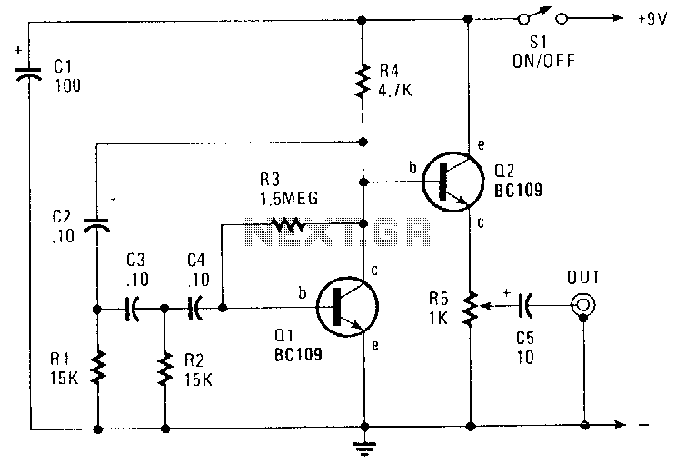
The Wien bridge oscillator is a highly regarded circuit in electronics for its ability to produce low-distortion sine waves. At its core, the oscillator utilizes a bridge configuration that allows for fine-tuning of frequency and amplitude. The key components include resistors, capacitors, and a variable gain element, which in this case is a small incandescent lamp. This lamp's resistance increases with temperature, providing a negative feedback mechanism that stabilizes the gain and ensures that the loop gain remains at unity during oscillation.
The frequency of oscillation is determined by the resistive and capacitive components in the circuit, specifically following the formula f = 1/(2πRC). The design incorporates four distinct frequency bands, allowing users to select from a range of 15 Hz to 150 kHz. Each band is adjusted using 20 k ohm potentiometers that are ganged together, enabling simultaneous control over the frequency while maintaining the desired output characteristics.
The output of the Wien bridge oscillator is designed to deliver voltages between 4 to 5 V under a load of 10 k ohm. This output level is crucial for interfacing with other circuits and ensuring that the oscillator can effectively drive loads without significant distortion. The feedback resistor (Rf) is strategically set to about 5% below the clipping point to prevent distortion and maintain a clean sine wave output.
In practical applications, the output from the oscillator can be coupled to other circuits, including DC circuits. To achieve this, a coupling capacitor is recommended to block any DC offset while allowing the AC signal to pass through. The output terminal is conveniently located at the center arm of the 5 k ohm output potentiometer, facilitating easy access for connections to external devices or circuits.
Overall, the Wien bridge oscillator is a versatile and efficient circuit for generating sine waves across a wide frequency range, making it valuable in various electronic applications, including audio synthesis, signal processing, and testing equipment.A Wien bridge oscillator produces sine waves with very low distortion level. The Wien bridge oscillator produces zero phase shift at only one frequency (f=1/2 RC) which will be the oscillation frequency. Stable oscillation can occur only if the loop gain remains at unity at the oscillation frequency. The circuit achieves this control by using th e positive temperature coefficient of a small lamp to regulate gain (Rf/RLAMP) as the oscillator attempts to vary its output. The oscillator shown here has four frequency bands covering about 15 Hz to 150 kHz. The frequency is continuously variable within each frequency range with ganged 20 k ohm potentiometers.
The oscillator draws only about 4. 0 mA from the 9-V batteries. Its output is from 4 to 5 V with a 10 k ohm load and the Rf (feedback resistor) is set at about 5% below the point of clipping. As shown, the center arm of the 5 k ohm output potentiometer is the output terminal. To couple the oscillator to a dc type circuit, a capacitor should be inserted in series with the output lead.
🔗 External reference
Related Circuits
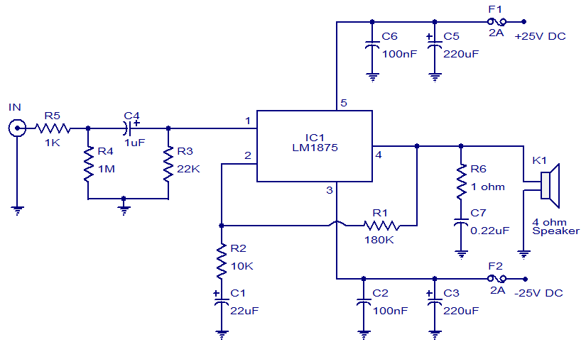
This weblog focuses on electronic circuit schematics, PCB design, DIY kits, and electronic project diagrams. The featured project is a 20W audio amplifier circuit based on the LM1875 audio amplifier IC from National Semiconductors. With a 25V power supply,...
Using two gates from a CMOS 4011 NAND chip, a simple square wave oscillator can be made. Alternatively, a CMOS 4001 chip can also be used, or a TTL equivalent. In this circuit, the mark-space ratio can also be...
This circuit generates a sinusoidal output of approximately 8 V peak-to-peak, which can be adjusted down to zero, operating at a frequency of about 500 Hz. The signal is produced by a phase-shift oscillator. The described circuit utilizes a phase-shift...
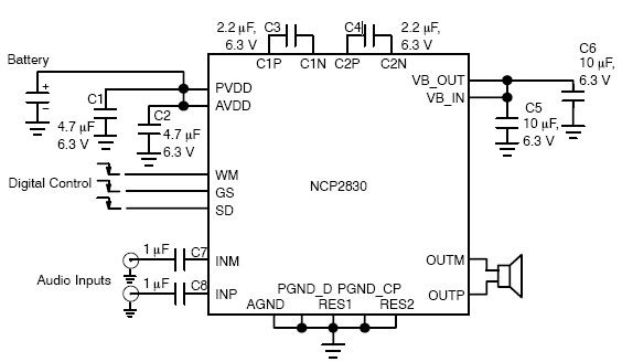
The NCP2830 audio power amplifier features high-quality audio performance with a total harmonic distortion plus noise (THD+N) of 0.04%. It offers low noise with a signal-to-noise ratio (SNR) of up to 100 dB and optimizes overall system efficiency, achieving...
This circuit indicates the power level delivered to a loudspeaker. A dual-color LED displays green at approximately 1 watt, orange at 1.5 watts, and bright red at levels exceeding 3 watts. The circuit is connected in parallel with the...
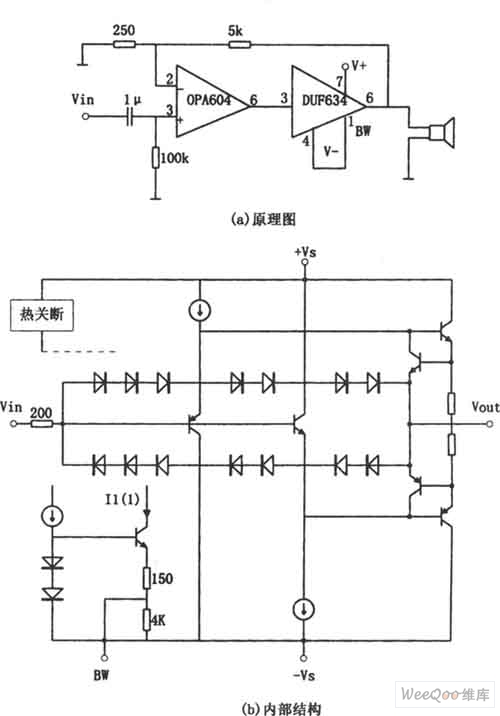
The provided image depicts a high-performance and low-power audio power amplifier circuit. The initial stage utilizes the MOSFET hi-fi operational amplifier OPA604, while the subsequent stage employs the high-speed buffer BUF634. Voltage series negative feedback is implemented between the...