
Square Wave Oscillator II

The square wave oscillator circuit utilizing a CMOS 4011 NAND gate IC is a straightforward yet effective design for generating oscillatory signals. The circuit typically employs two of the four available NAND gates within the 4011 chip, configured in a feedback arrangement that enables oscillation. The fundamental operation relies on the charging and discharging of a capacitor through resistors, which determines the frequency and duty cycle of the output waveform.
In this configuration, the output frequency (f) of the oscillator can be calculated using the formula:
\[ f = \frac{1}{2 \cdot R \cdot C \cdot \ln(2)} \]
where R is the resistance in ohms and C is the capacitance in farads. The choice of resistor values and capacitor determines not only the frequency but also the mark-space ratio of the output waveform. By adjusting the resistors, the time the output signal remains high (mark time) versus the time it remains low (space time) can be independently controlled, allowing for versatile applications in timing circuits.
The rise and fall times of the output pulses, which are crucial for determining the quality of the square wave, are influenced by the operating voltage supplied to the IC, as well as the specific characteristics of the chosen IC. Typically, these transition times are in the range of tens of nanoseconds, making this circuit suitable for applications requiring fast switching speeds, such as clock signals in digital circuits.
When implementing this oscillator, attention must be paid to the power supply decoupling to ensure stable operation, as fluctuations in the supply voltage can affect the performance and reliability of the generated waveform. Additionally, proper layout considerations should be taken into account to minimize parasitic capacitances and inductances, which can distort the output signal.
Overall, this simple square wave oscillator circuit using CMOS technology is an essential building block in various electronic applications, providing a reliable means of generating periodic signals.Using two gates from a CMOS 4011 NAND chip, a simple aquarewave oscillator can br made. Alternatively a CMOS 4001 chip can also be used, or a TTL equivalent. In this circuit the mark space ratio can also be independantly controlled by varying the value of the resistors. The rise and fall times of the output pulses depend on the operating voltage of the IC and type of IC, but will be typically in the order on tens of nanoseconds. 🔗 External reference
Related Circuits
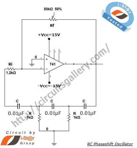
A phase-shifted oscillator can be constructed using a basic operational amplifier (op-amp), three resistors, and three capacitors. One of the resistors should be adjustable, while the other components should have the same value. This oscillator design exhibits low distortion...
Regenerative feedback at capacitor C allows the oscillator to complete its timing cycle instead of shutting off immediately. The integrated circuit (IC) used was a CD4011AE, although an equivalent IC will also function. The described circuit utilizes regenerative feedback to...
The use of a quarter-wave parallel-wire line as a tuning unit has been discussed in the chapter on Short-Lines, where it was pointed out that these circuits have comparatively high Q even at higher frequencies. Their significant length (approximately...
To achieve a 50% duty cycle using a 555 timer IC, two diodes can be employed to isolate the charging and discharging paths. Alternatively, it is also possible to configure the circuit without diodes. The 555 timer IC is a...
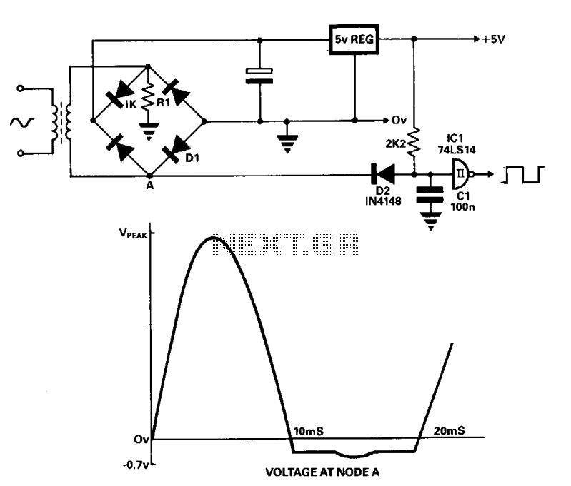
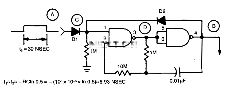
A line frequency square wave with a 1:1 duty cycle can be generated using only three components and a buffer from the power supply. During the alternate half-cycle, point A is clamped to approximately -0.7 V by diode D1...
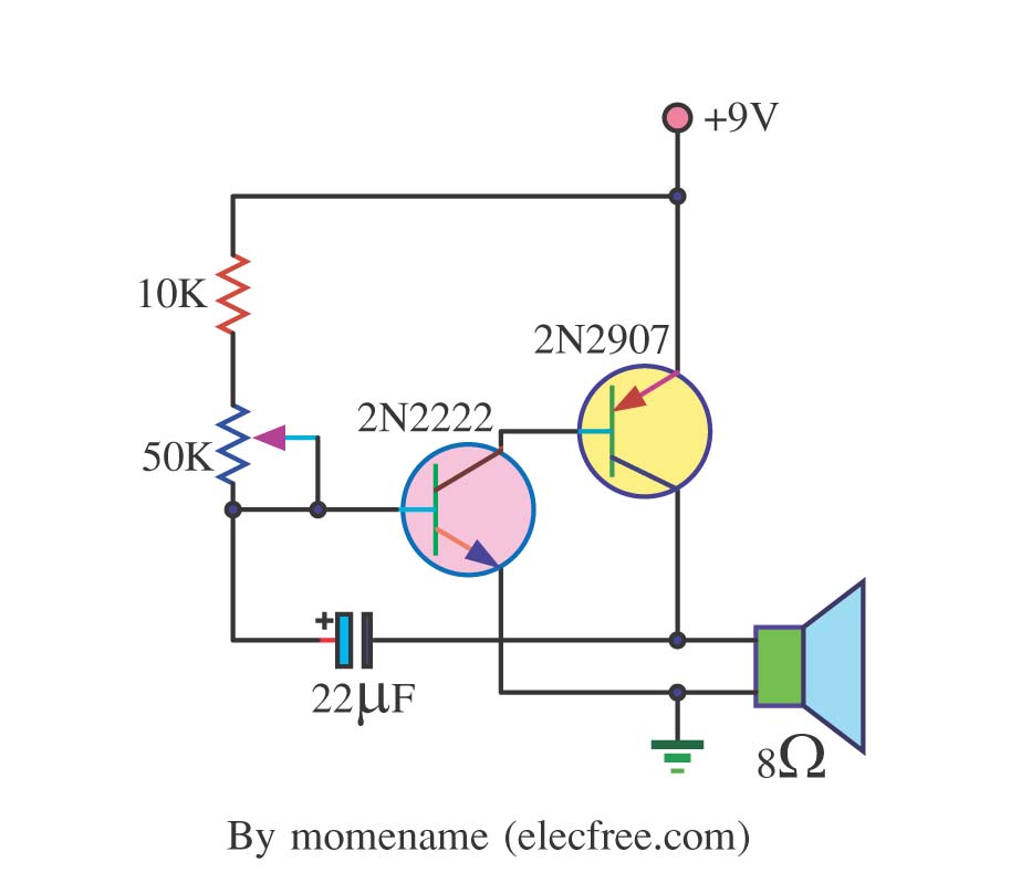
This is a simple tone oscillator generator. It uses the transistors 2N2222 and 2N2907 as the main components. The tone sound is controlled with a 50K ohm resistor (R2) and an 8-ohm speaker is utilized. The tone oscillator generator circuit...