
OPA604 High Performance and Small Power Audio Amplifier

The audio power amplifier circuit is designed to achieve high fidelity while maintaining low power consumption. The OPA604 operational amplifier serves as the first amplification stage, providing low noise and high output quality. Its characteristics make it suitable for audio applications where signal integrity is paramount. The use of a MOSFET configuration allows for better performance at higher frequencies and improved linearity.
The second stage of amplification is realized using the BUF634 buffer. This component is specifically designed to drive capacitive loads and provides a high current output, which is essential for driving speakers or other low-impedance loads. The BUF634's internal architecture includes a series of transistors configured to enhance speed and reduce distortion, ensuring that the amplified signal retains its fidelity.
The voltage gain of the circuit is crucial for determining the output signal level relative to the input. The feedback network, composed of the 5kΩ and 250Ω resistors, establishes a gain of approximately 21 times, calculated using the formula for non-inverting amplifiers. This gain is suitable for many audio applications, providing sufficient amplification without introducing excessive noise or distortion.
The implementation of voltage series negative feedback between the two amplifier stages is significant for stability and linearity. By feeding a portion of the output back to the input, the circuit can reduce distortion and improve overall performance. This feedback mechanism ensures that the amplifier operates within its optimal range, enhancing sound quality.
In summary, this audio power amplifier circuit effectively combines the OPA604 and BUF634 to create a high-performance, low-power solution for audio amplification. Its design principles, including careful selection of component values and feedback mechanisms, contribute to its capability to deliver high-quality audio signals suitable for various applications.The above picture is high performance and small power audio power amplifier circuit. This circuit`s former level uses the mosfet hi-fi op-amp OPA604 and next level adopts high-speed buffer BUF634 and voltage series negative feedback is used between two levels amplifiers. This circuit voltage magnification depends on two resistances (5k © and 250 ©) of feedback branchs and its value is l+5k © 250 ©‰ 21 times. BUF634 is high-speed buffers and itsinternal structure simplified circuit is shown in figure (b). 🔗 External reference
Related Circuits
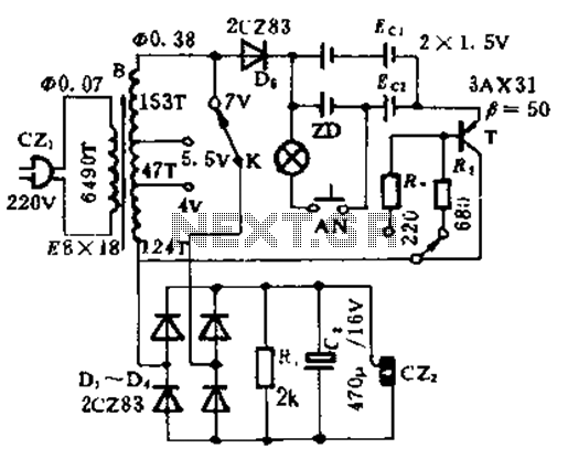
This circuit is designed for high current applications using nickel-cadmium rechargeable batteries, and it can also function as a general low-voltage DC power supply. The circuit consists of a charging section and a DC output section. K2 serves as...
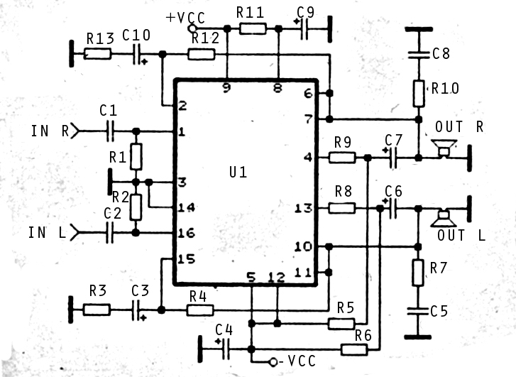
The audio amplifier circuit is highly suitable for home use, particularly with subwoofer or woofer speakers. Commonly referred to as a home amplifier, these audio amplifiers are based on integrated circuits (ICs), specifically the STK series, which includes models...
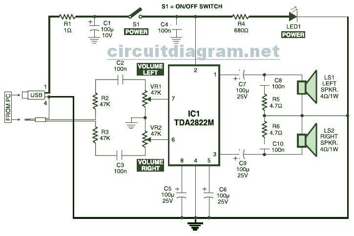
USB Powered Stereo PC Multimedia Speaker Circuit Diagram. This circuit is powered by a 5V DC source obtainable from the USB port of a computer. When the electrical power switch S1 is turned to the "on" position, the 5V...
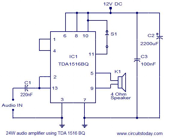
The circuit diagram illustrates a simple 24W mono amplifier utilizing the TDA1516 integrated circuit. The TDA1516 is a Class B power amplifier packaged in a 13-pin SIL configuration. This integrated circuit includes several beneficial features, including short circuit protection,...

This is a low watt audio amplifier with a different technique in design. The 1.8K resistor has been connected to output of the circuit instead of VCC line. The output power of the circuit is about 250mW on an...
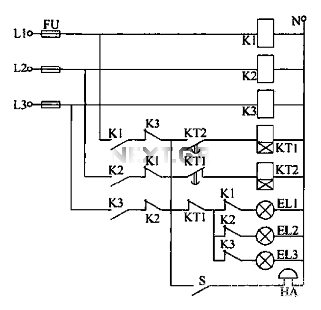
Any power supply and distribution sector should include phase sequence detection to ensure that the power supply phase sequence remains stable and unchanged. Additionally, any irreversible electromechanical product should also incorporate phase sequence detection to verify the phase sequence...