
Audio distribution electronic project circuit diagram

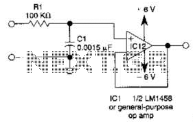
The audio distribution circuit utilizes TL064 or TL06 operational amplifiers, which are quad op-amps known for their low noise and high performance. These components are ideal for audio applications due to their ability to amplify weak audio signals without introducing significant distortion or noise. The circuit typically includes a power supply section, input and output stages, and feedback networks to ensure stability and gain control.
The design may incorporate resistors and capacitors to set the gain of the operational amplifiers and to filter out unwanted frequencies. Input connections can be made for various audio sources, while output connections are designed to drive speakers or further processing stages. The layout should ensure minimal interference and optimal signal integrity, often achieved through careful routing of traces and placement of components.
For practical implementation, a PCB (Printed Circuit Board) can be designed to accommodate all components, ensuring a compact and reliable assembly. Proper grounding techniques should be employed to minimize noise and improve overall performance. Additionally, consideration should be given to the thermal management of the op-amps, as excessive heat can affect their operation.
Overall, this audio distribution circuit is suitable for applications in home theaters, public address systems, and musical performance setups, providing high-quality audio signal distribution with minimal loss and distortion.This audio distribution electronic project circuit diagram is designed using the TL064 or TL06 operational amplifiers and some other common electronic parts. 🔗 External reference
Related Circuits
The LM35 Smart Heater Controller Schematic features a compact circuit designed around the well-known 3-Pin Integrated Temperature Sensor LM35 (IC1) from National Semiconductor. Additionally, a widely used BiMOS Op-amp CA3140 (IC2) is employed to monitor the temperature sensor's output,...
This simple filter utilizes an RC section as the filter element, incorporating a voltage follower to manage other frequencies. The -3 dB point is calculated as 1/(6.28 * RXCV), resulting in a response that drops 6 dB per octave...
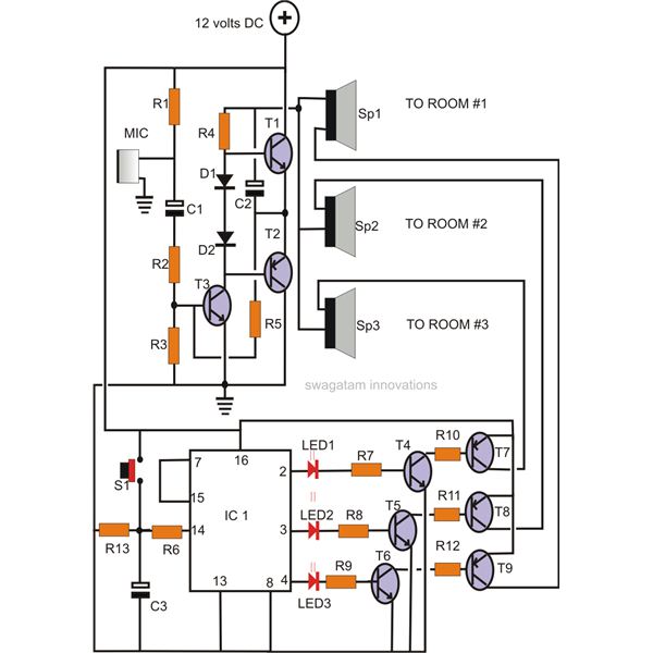
A home intercom system can be constructed using a versatile circuit design. This system allows communication across up to ten different locations or rooms discreetly. It utilizes a single changeover switch for selecting the desired location, replacing the traditional...
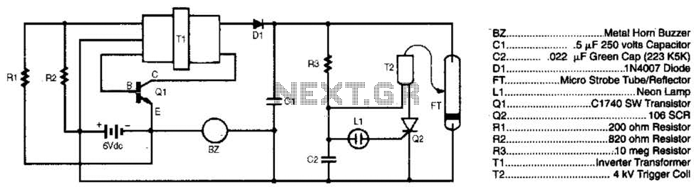
The burglar chaser is an effective accessory for any alarm system. It produces intense flashes of white light and generates a loud, irritating sound using a metal horn buzzer. Transformer T1 is connected to Q1, R1, and R2 to...
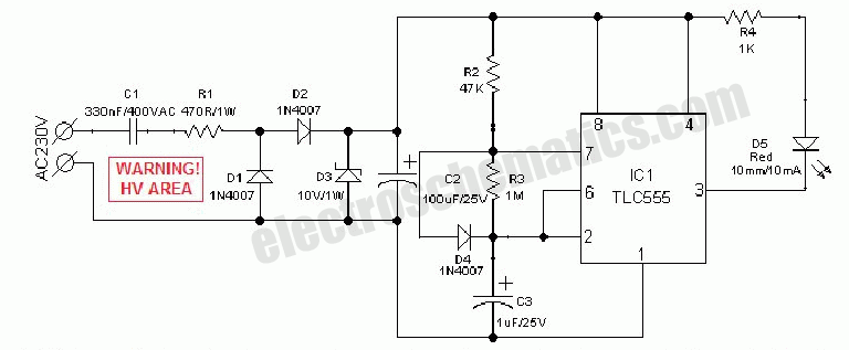
An AC mains operated single LED flasher circuit is constructed using the widely utilized CMOS timer chip TLC555. The entire circuit is powered directly from the 230VAC grid supply via a capacitive potential divider and associated components. This compact...

The circuit depicted in the figure comprises a PGA103 programmable gain instrumentation amplifier. This design utilizes the PGA205 and PGA103 in a cascading configuration, resulting in a total gain for the amplifier. The gain is determined by the product...