
audio level meter circuit using lm3915

The audio level meter circuit designed using the LM3915 is a straightforward and efficient solution for visualizing audio signal levels. The LM3915 IC operates in bar graph mode, illuminating a series of LEDs that represent the amplitude of the audio signal. This feature is particularly useful in audio engineering, sound mixing, and various applications where monitoring audio levels is crucial to prevent distortion or clipping.
The circuit's design can be broken down into several key components. The LM3915 serves as the heart of the meter, where it processes the incoming audio signal. The input stage includes a high-impedance buffer, which is essential for preventing loading effects on the audio source. This feature allows the circuit to accurately sense low-level signals without introducing distortion or altering the signal characteristics.
The programmable LED current drive feature of the LM3915 allows for customization of brightness levels, enhancing visibility under different lighting conditions. By adjusting the reference voltage, the user can calibrate the meter to suit specific application requirements, ensuring precise readings across various audio levels.
The ten-step voltage divider within the IC enables the display of audio levels in a logarithmic scale, which is more representative of human hearing perception. This logarithmic response is crucial for applications such as live sound reinforcement, where audio levels can vary significantly.
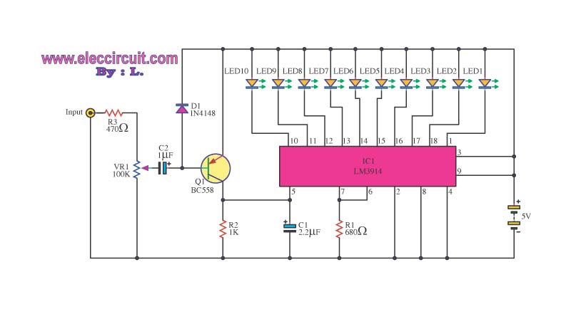
Additionally, the circuit can operate safely with input voltages up to 35V, making it robust for various environments. This characteristic, combined with the IC's accuracy of better than 1 dB, positions the audio level meter as a reliable tool for audio professionals. The simplicity of the design, requiring only a few external components, further enhances its appeal, allowing for easy integration into larger audio systems or standalone applications.This is a simple design of audio level meter. This circuit uses just one IC and a very few number of external components. This circuit is based on LM3915 as controller in the operation of the audio level meter circuit. It displays the audio level in terms of 10 LEDs. This is the figure of the circuit. The input voltage can vary from 12V to 20V, bu t suggested voltage is 12V. The LM3915 is a monolithic integrated circuit that senses analog voltage levels and drives ten LEDs providing a logarithmic 3 dB/step analog display. LED current drive is regulated and programmable, eliminating the need for current limiting resistors.
The IC contains an adjustable voltage reference and an accurate ten-step voltage divider. The high-impedance input buffer accepts signals down to ground and up to within 1. 5V of the positive supply. Further, it needs no protection against inputs of 35V. The input buffer drives 10 individual comparators referenced to the precision divider. Accuracy is typically better than 1 dB. 🔗 External reference
Related Circuits
A computerized infrared remote project is a simple device designed for recording and playing back streams of infrared data, specifically the codes transmitted by remote controls. Software is provided for use in both DOS and Windows environments, along with...
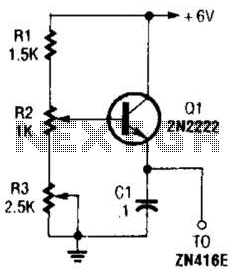
This regulator can be used with a +6-V source to supply the ZN416E low-voltage TRF radio receiver IC with the necessary +1.5 V. R3 sets the output voltage. The circuit utilizes a voltage regulator designed to convert a +6 V...
The MCU is an ATMEL 89C4051 CMOS Microcontroller featuring 4kB of code memory, 128 bytes of on-chip RAM, and 8-bit Port1 and Port3. The A/D chip is a HARRIS CA3162, which functions as a 3-digit digital voltmeter (DVM). This...
The circuit automatically lights a bulb upon the arrival of a telephone ring and simultaneously mutes the audio from the music system or TV while the telephone handset is off-hook. The lighting of the bulb not only indicates an...
This DC to DC converter increases a DC voltage to nearly double its original value and is useful for elevating the output voltage of solar batteries to the required level. The DC to DC converter operates on the principle of...
This is a simple light-running circuit synchronized with music. The circuit is straightforward, operating in mono, and requires only a few components. It can be connected to the output of a CD player. The described circuit utilizes a basic audio...