
Audio peak Indicator

The described circuit functions as an audio waveform detector and indicator, suitable for applications where audio signals need to be monitored from a distance or in environments where sound cannot be heard. The circuit design incorporates a few key components to achieve its functionality.
At the core of the circuit is an operational amplifier (op-amp) configured as an inverting amplifier with a gain of 100. This configuration allows for the amplification of low-level audio signals, making it possible to detect the presence of an audio waveform. The input stage receives the audio signal from the loudspeaker terminals, where it can be directly connected.
The use of a 10kΩ potentiometer as a level control is crucial in this design. This component allows for the adjustment of the sensitivity of the circuit, enabling the user to set the threshold at which the LED indicator will illuminate. When the audio signal exceeds this threshold, the amplified output from the op-amp will activate the LED, providing a visual cue that an audio signal is present.
The LED serves as a simple yet effective indicator, providing immediate feedback to the user regarding the status of the audio source. The circuit should be powered with an appropriate voltage supply that matches the specifications of the op-amp being used, ensuring reliable operation.
Additional components may include resistors to set the gain of the op-amp, capacitors for filtering to prevent noise interference, and possibly a diode to protect against reverse polarity. Overall, this circuit is an efficient solution for remote audio monitoring, making it suitable for various applications in security systems, sound engineering, and audio testing environments.This circuit can be used to remotely monitor a loudspeaker, alarm, or audio source for presence of an audio waveform. It can also be directly connected across loudspeaker terminals used as a peak indicator. If you need to monitor some audio signal at a location that is either soundproof are too far away to actually hear the signal then you can use a circuit similar to this one.
A remote indication that the audio source is active is provided visually, here in the form of a LED. Referring to the above circuit, the 10k preset is a level control which should be adjusted so that when the source ( audio signal or alarm ) is producing the desired amount of noise, the LED lights. The input stage is an inverting x100 amplifier made with 🔗 External reference
Related Circuits
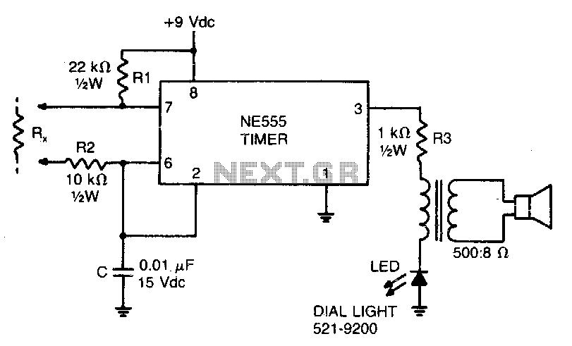
This low-current audio continuity tester indicates the unknown resistance value by the frequency of the audio tone. A high tone indicates a low resistance, while a tone of a few pulses per second indicates a resistance as high as...
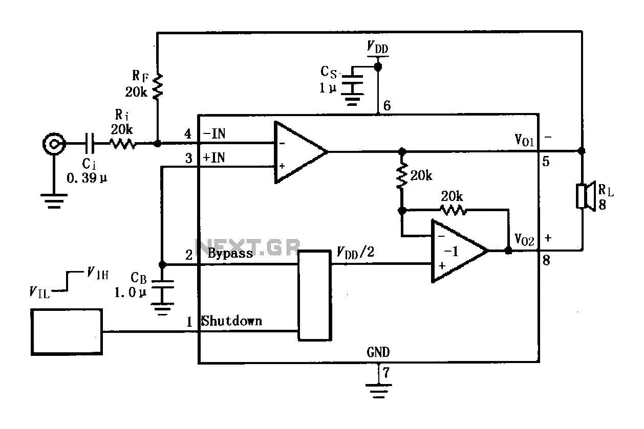
The LM4819 audio power amplifier is designed to amplify audio signals. An audio signal is input through the coupling capacitor (Ci) and the resistor (Ri) applied to the inverting input terminal (pin 3) of the amplifier. The inverting input...
For many applications, there's no substitute for sheer power - low efficiency speakers, outdoor sound systems, or maybe you like the full flavor of the dynamic range of a high power amp. Whatever your requirement, this super power module...
These accessories are low-cost, high-speed, bifet-input operational amplifiers utilizing internally compensated voltage (BI-FET II technology). They require low supply voltages while offering a wide gain bandwidth product and fast slew rate. Additionally, well-matched high voltage JFET input devices accommodate...
The entire project was developed at the request of a friend. Its purpose is to remotely monitor the water level in a metal tank located in the attic using a simple control unit placed in the kitchen, several floors...

An audio power amplifier circuit for a 3-watt stereo amplifier using the MAX 7910 IC is explained below. The audio power amplifier circuit utilizing the MAX 7910 IC is designed to deliver a maximum output power of 3 watts per...