
Variable power supply

The circuit described operates as a power supply that converts high-voltage AC to a lower DC voltage suitable for various electronic applications. The transformer T1 is central to this process, stepping down the input AC voltage (either 115VAC or 220VAC) to approximately 8VAC. This lower AC voltage is then fed into a bridge rectifier (BR1), which consists of four diodes arranged to efficiently convert AC to DC. The expected output from the rectifier is around 11.52V DC, after accounting for diode forward voltage drops.
Capacitor C1, rated at 1000µF and 25V, serves the critical function of filtering the DC output to reduce ripple voltage, ensuring a smoother DC signal for downstream components. In cases where the output is found to be excessively noisy or has unacceptable ripple, an additional electrolytic capacitor can be added across the output terminals. This additional capacitor should have a value between 10µF and 100µF with a voltage rating of at least 25V to adequately handle the output voltage.
The circuit’s output voltage is adjustable, facilitated by a 10K potentiometer (P1). This potentiometer allows for fine-tuning of the output voltage while keeping the output current constant, which is essential for applications requiring stable performance despite varying load conditions.
The transistor Q1, which can be a 2N1613 or NTE128, is used to regulate the output voltage and is housed in a TO-39 case for effective thermal management. It is mounted on a heatsink (referred to as "coolrib") to dissipate heat generated during operation, ensuring reliability and longevity of the component.
Resistors R1 and R2, with values of 470 ohms and 1K ohms respectively, are used in the circuit for biasing and stability purposes. R1 is a 5% tolerance resistor, which implies its resistance can vary by 5% from its nominal value, while R2 serves a similar purpose with the same tolerance.
Capacitor C2, with a value of 0.1µF (100nF), is a ceramic capacitor that is typically used for high-frequency noise filtering, enhancing the overall performance of the circuit by reducing high-frequency interference.
Overall, this circuit design provides a versatile and adjustable power supply solution suitable for various electronic projects, ensuring stable voltage and current output with provisions for noise reduction and thermal management.T1 steps down AC voltage from 115VAC (or 220VAC) to about 8VAC and is then rectified via bridge rectifier BR1 to about 11.52Vdc. C1 filters off the AC ripple. If you find the circuit output too noisy add another electrolytic capacitor over the output terminals.
Value can be between 10 and 100uF/25V. The output voltage is variable with the 10K-potentiometer while keeping the current constant. T1 = 115/8 VAC transformer. Center Tap not needed. Q1 = 2N1613, NTE128, or substitute. (TO-39 case) On coolrib! BR1 = 40V, 4A. (Check max current of your mini-drill and add 2A) R1 = 470 ohm, 5% R2 = 1K, 5% P1 = Potentiometer, 10K C1 = 1000uF, 25V, electrolytic C2 = 0.1uF (100nF), ceramic 🔗 External reference
Related Circuits
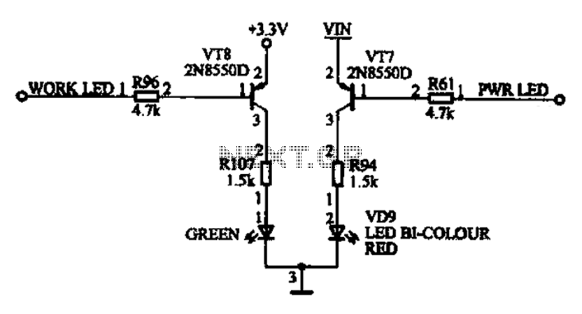
The ACER PM02 MP4 machine features a voltage status indicator circuit. When power is supplied, a red LED illuminates, indicating that the device is powered on. Upon entering operational mode, a green LED lights up. The voltage status indicator circuit...
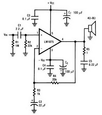
The amplifier circuit can be constructed using the LM1875 power amplifier IC. The LM1875 is a single-chip power amplifier from National Semiconductor. This 20-watt audio amplifier is characterized by low power consumption while delivering high-quality sound suitable for use...
The following circuit illustrates a Power Amplifier Circuit Diagram utilizing a 2N3055 transistor. Features include a 500-ohm current and an optimal voltage of 50V. The power amplifier circuit based on the 2N3055 transistor is designed to deliver significant output power,...
70 W switching power supply utilizing the KA2S0880 integrated circuit. Refer to the specified page for an explanation of the associated circuit diagram. The 70 W switching power supply designed with the KA2S0880 integrated circuit (IC) is a versatile solution...
This circuit provides automatic current limiting up to 8.4 A. Unlike current limiters that use only a resistor, this current limiting circuit does not drop the voltage significantly or keeps the voltage drop to a minimum until a specific...
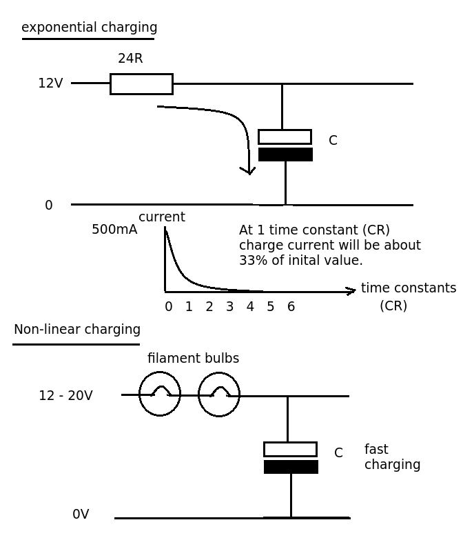
Designing a simple current limiter that charges a large 4.7mF capacitor with a charge current of approximately 500mA from a supply voltage of 10-20V. The dilemma is that there are existing MMBT2222A transistors available, which would be preferable to...