
Audio Processor Circuit

The audio processor circuit is centered around the SSM2045, which is renowned for its ability to provide dynamic range compression and is particularly well-suited for enhancing electronic music signals. The SSM2045 operates by adjusting the gain of the audio signal based on its amplitude, effectively compressing louder sounds and amplifying quieter ones. This functionality is crucial in electronic music, where maintaining audio clarity and balance is essential.
In conjunction with the SSM2045, the 741 op-amp is employed to perform various signal conditioning tasks. The 741 is a versatile op-amp capable of providing amplification, filtering, and buffering of audio signals. It can be configured in different configurations such as inverting, non-inverting, or as a voltage follower, depending on the specific requirements of the circuit design.
The circuit layout typically includes input and output connectors for audio signals, power supply connections for both the SSM2045 and the 741 op-amp, and passive components such as resistors and capacitors that set the gain and frequency response of the circuit. The use of high-quality components is recommended to minimize noise and distortion, ensuring optimal audio performance.
In summary, this audio processor circuit effectively combines the specialized capabilities of the SSM2045 with the general-purpose functionality of the 741 op-amp to create a robust solution for processing electronic music signals. The design considerations should focus on achieving the desired dynamic range and audio fidelity, making it suitable for both live performances and studio applications.This audio processor circuit features the SSM2045 IC which was developed specially for electronic music applications and the 741 opamp IC. The circuit is c.. 🔗 External reference
Related Circuits
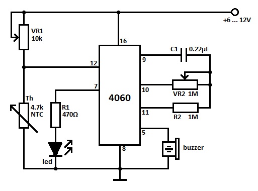
Two heat sensor circuits are presented. The first circuit is constructed using a 4060 integrated circuit (IC), while the second circuit is simpler and contains fewer components. This serves as a conceptual idea. The first heat sensor circuit utilizing the...

A circuit is needed to drive three or more LEDs at a current of 200-350mA each, with the capability to randomly flash or strobe them at a frequency of 5-20Hz. The input power should be low-voltage DC, with a...
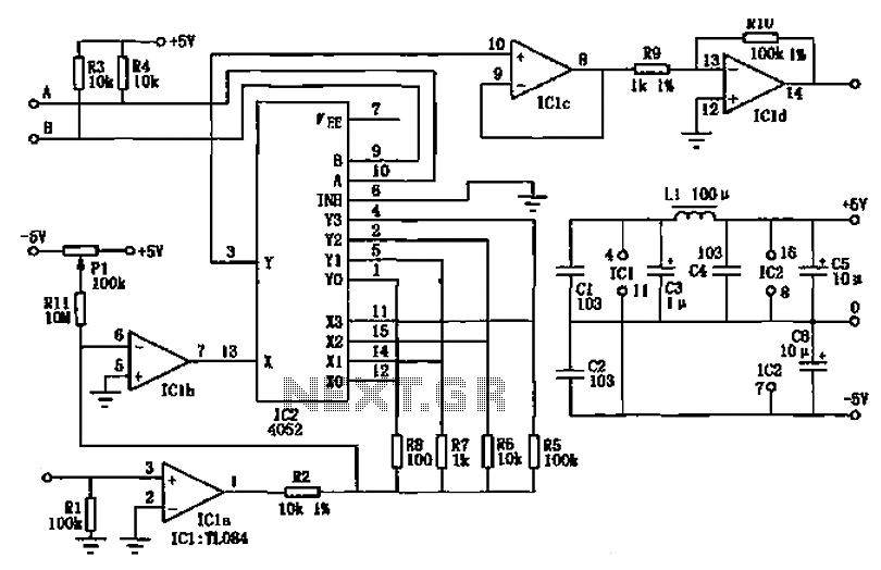
The PGA103 is designed with a wide input voltage range. It utilizes a voltage divider circuit consisting of a 11.3kΩ resistor and a 102kΩ resistor, achieving a division ratio of approximately 1/10. For instance, when the input voltage is...
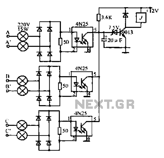
A, B, and C are used for a large power split-phase system. The A + BC range generator phase line features an A-A indole path string containing two 220V/15W bulbs. The bulbs recover based on macro instructions from J...
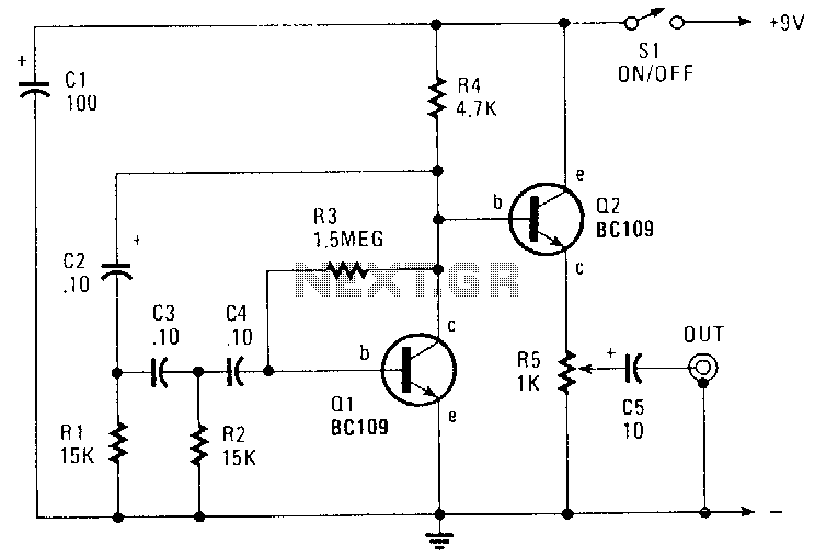
This circuit generates a sinusoidal output of approximately 8 V peak-to-peak, which can be adjusted down to zero, operating at a frequency of about 500 Hz. The signal is produced by a phase-shift oscillator. The described circuit utilizes a phase-shift...
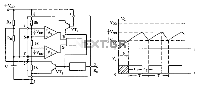
The circuit diagram illustrates the 555 timer (or 556 timer in half configuration) configured in astable multivibrator mode. It features three resistive and capacitive elements connected as shown. In one-shot mode, the trigger terminal (pin 2) is connected to...