
Heat Sensor Circuit

The first heat sensor circuit utilizing the 4060 IC is based on the principle of temperature detection through a thermistor or similar temperature-sensitive component. The 4060 IC functions as an oscillator, generating a frequency output that varies with temperature changes. The thermistor is connected to a resistor, forming a voltage divider that provides an input to the 4060. As the temperature increases or decreases, the resistance of the thermistor changes, thereby altering the voltage at the input of the IC. This change in voltage leads to a corresponding change in the frequency output, which can be monitored or used to trigger other components in the circuit, such as alarms or indicators.
The second heat sensor circuit is designed to be more straightforward, likely employing a basic transistor or operational amplifier configuration to sense temperature changes. This circuit may use a thermistor directly connected to a comparator circuit, where the output changes state based on a predefined temperature threshold. Fewer components in this design make it easier to assemble and potentially more cost-effective, though it may lack some of the advanced features provided by the 4060-based circuit.
Both circuits can be utilized in various applications, such as temperature monitoring systems, fire detection systems, and HVAC controls, showcasing the versatility of heat sensing technologies in electronic design.Here are 2 heat sensor circuits, first one is build with the 4060 IC, the second one is simpler than the one before and has fewer components. It is an idea.. 🔗 External reference
Related Circuits
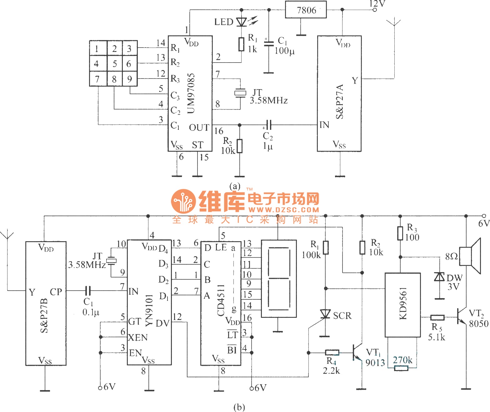
It utilizes a DTMF encoder output, which generates a dual-tone multi-frequency coded signal to modulate the transmitted carrier frequency. This configuration allows for the formation of a DTMF-encoded radio paging system. The circuit incorporates a DTMF encoding chip, UM97085,...

This circuit generates sine and square wave signals with frequencies ranging from below 20 Hz to above 20 kHz. The advantage of this circuit diagram is that the output frequency can be adjusted by varying the variable resistor R6. The...
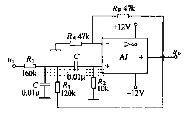
A band-pass filter permits only signals within a specified frequency range to pass through, while attenuating or suppressing those outside this range. This is characterized by a lower frequency limit and an upper frequency limit. A typical implementation is...
If you are expecting an important visitor but need to step out for a moment, an electronic doorbell memory can be useful to check whether someone rang while you were away. While it cannot confirm if it was the...

This is an automatic light dimmer circuit. There is no need to manually adjust the brightness of the lights. This circuit is highly convenient, as it utilizes a light-dependent resistor (LDR) to detect external light levels. The automatic light dimmer...
The microphone preamplifier circuit design presented in this schematic utilizes the SSM2015 produced by Precision Monolithics Inc. (PMI), which offers high amplification. The SSM2015 is a low-noise, low-distortion integrated circuit designed specifically for microphone preamplification. It features a differential input...