
Audio Signal Clipping Indicator

The window comparator circuit utilizes two operational amplifiers (op-amps) configured to create a defined voltage range, or "window," within which an input signal must fall for the output to indicate a specific state. The circuit employs IC1, which houses the two op-amps, to achieve this functionality efficiently.
The first op-amp is configured as a non-inverting comparator, with its non-inverting input connected to a reference voltage, typically set by a voltage divider. The inverting input is connected to the input signal. When the input signal exceeds the reference voltage, the output of this op-amp transitions to a high state, indicating that the input has crossed the upper threshold of the window.
Conversely, the second op-amp is configured as an inverting comparator. Its inverting input is connected to a lower reference voltage, also established by a voltage divider, while the non-inverting input receives the input signal. When the input signal drops below this lower reference voltage, the output of the second op-amp switches to a high state, indicating that the input has fallen below the lower threshold of the window.
The outputs of both op-amps can be connected to a logic gate or a microcontroller to provide a clear indication of whether the input signal is within the defined window. This configuration allows for precise detection of signals that fall within a specific range, making it suitable for applications in signal conditioning, level detection, and various control systems. The symmetrical design ensures that both upper and lower thresholds are equally significant, providing a balanced response to the input signal variations.A window comparator formed by two op-amps packaged into IC1 is the heart of the circuit below. With this technique, we can detect precisely and symmetrically.. 🔗 External reference
Related Circuits

The debate continues regarding whether valves or transistors are superior. This discussion will not be addressed here. However, if one cannot make their… The comparison between valves (vacuum tubes) and transistors has been a longstanding topic in the field of...
A comprehensive understanding is required to design an inverter effectively. The design of the circuit is largely influenced by the availability of a custom-made transformer. To design an inverter, various factors must be considered, including the input and output voltage...
A 6-watt audio amplifier circuit utilizing the TDA2613 is presented here. The TDA2613 is an integrated Hi-Fi audio amplifier IC produced by Philips Semiconductors. The IC is designed for high-quality audio amplification. The circuit features the TDA2613 IC, which is...
Given the variety of equipment in modern home entertainment systems, the ability to adjust the gain of both audio and video signals has become essential. This particular circuit has proven to be very useful when used alongside the General...
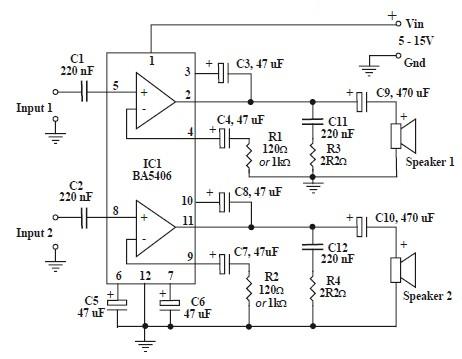
This circuit is based on the BA5406 audio integrated circuit and is capable of providing a maximum output power of 3 watts per channel. This audio circuit is designed for various applications requiring amplified sound output. The BA5406 is a...

A passive high-pass filter has been added after the output of the operational amplifier (op-amp) to eliminate DC offset, with the op-amp powered by +12V and the negative supply at 0V. A feedback resistor (Rf) of 500K Ohms is...