
Simple Hybrid Audio Amplifier

The comparison between valves (vacuum tubes) and transistors has been a longstanding topic in the field of electronics, each having its unique advantages and applications. Valves are known for their warm sound quality and high voltage handling capabilities, making them popular in audio amplification and vintage equipment. Conversely, transistors offer advantages such as compact size, lower power consumption, and greater reliability, which have led to their dominance in modern electronic devices.
In a comprehensive electronic schematic, the choice between using valves or transistors can significantly influence the design parameters. For instance, a valve-based amplifier circuit would typically include components such as high-voltage power supplies, filament transformers for heating the cathodes, and output transformers to match the impedance of speakers. These circuits often require careful layout considerations to manage heat dissipation and electromagnetic interference.
On the other hand, a transistor-based amplifier circuit would utilize low-voltage power supplies and include biasing resistors to set the operating point of the transistors. The schematic would also incorporate capacitors for coupling and decoupling signals, ensuring that the audio fidelity remains intact while preventing DC bias from affecting subsequent stages.
When designing a circuit, it is essential to evaluate the intended application, desired sound characteristics, and physical constraints. This evaluation will guide the selection of either valves or transistors, ultimately influencing the performance, reliability, and user experience of the electronic device. Each technology presents distinct challenges and benefits that must be carefully considered during the design process.The debate still goes on as to which are better, valves or transistors. We don t intend to get involved in that argument here. But if you can t make your.. 🔗 External reference
Related Circuits
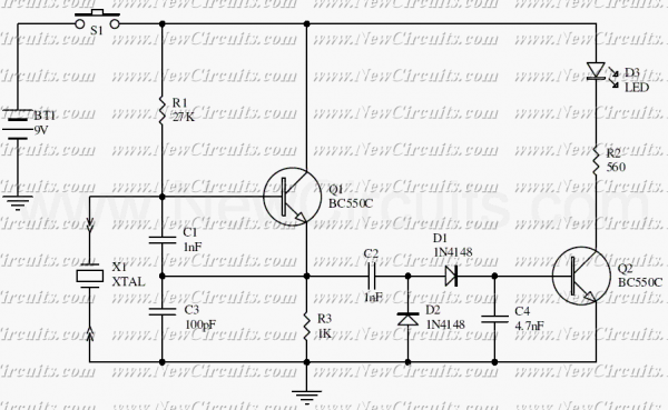
This is a simple XTal tester circuit. T1 and XTal have formed an oscillator. C1 and C2 are voltage divider for oscillator. if the XTal is safe, the oscillator will work well and its output voltage will be rectified...
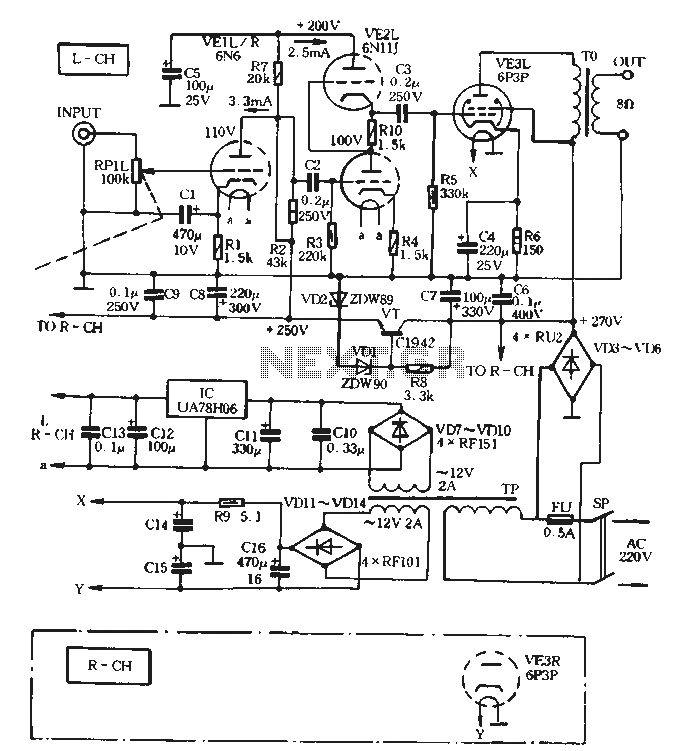
The VE1 preamplifier utilizes a low muscle, low resistance double triode 6N6 configuration, with separate halves for the left and right audio channels. The design operates within the CPI framework. It promotes the use of high-level VE2 household low...
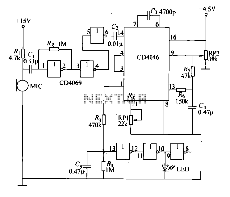
Each issue produces a specific frequency of sound, and the audio remote control will switch states based on these frequencies. The circuit is designed to detect other frequencies emitted by environmental sounds with strong anti-interference capabilities. The circuit operates...
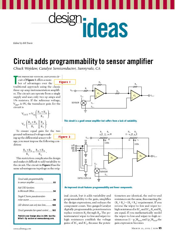
This tutorial provides information related to sensor amplifiers, schematics, and noise. It presents a discussion around sensors and their outputs. Sensor amplifiers are critical components in various electronic systems, especially in applications where signals from sensors need to be conditioned...
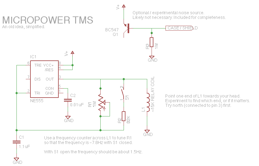
Let's face it, not every day is the greatest. Sometimes, one may not feel like doing much of anything. Wouldn't it be nice if there was a way to change brain waves at the push of a button? Transcranial...
The XLR connector facilitates the connection of the microphone's output to the preamplifier circuit. This preamplifier was designed and constructed by Electrical Engineers using discrete components. The signal from the preamplifier is subsequently fed to the Maxim Class-D amplifier....