
audio tone control 2 transistor circuit

The circuit utilizes the BC109C transistor as a buffer stage, which is essential for maintaining high input impedance while minimizing loading effects on preceding stages. With an input impedance of approximately 250k, this transistor ensures that the signal source is not significantly affected by the circuit's characteristics, allowing for a faithful reproduction of the input signal. The voltage gain of slightly less than unity ensures that the output signal remains closely aligned with the input, preserving the integrity of the audio signal.
The Baxendall tone control circuit is a well-known passive equalization design that allows for the adjustment of audio frequencies without introducing significant distortion. In this configuration, all audio frequencies are attenuated, and the specific response characteristics can be manipulated by adjusting the positions of the tone control potentiometers and the reactance values of the capacitors used in the circuit. The interaction between the control settings and the capacitors determines the overall tonal balance, enabling the user to tailor the audio output according to their preferences.
The final transistor stage is designed to provide a modest gain of approximately 3 times, which is sufficient to drive subsequent audio amplification stages effectively. The output is optimized for connection to amplifiers with input impedances between 10k and 250k, ensuring compatibility with a wide range of audio equipment. The use of linear type potentiometers for the tone controls allows for smooth and precise adjustments, making it easier for users to achieve their desired sound profile. This combination of design elements results in a versatile and effective audio processing circuit suitable for various applications in audio engineering.The first BC109C transistor is acting as a buffer. It provides the circuit with a high input impedance, around 250k has a voltage gain of slightly less than unity. As the Baxendall tone control circuit is a passive design, all audio frequencies are attenuated. The position of the controls and reactance of the capacitors alters the audio response. The last transistor provides a slight boost of about 3x. The output is designed to feed an amplifier with input impedance of 10k to 250k. Both tone controls should be linear type Potentiometers. 🔗 External reference
Related Circuits
The circuit does not fail under slight variations, even if the input/output electric current characteristics are exceeded. Failure occurs only during a short circuit or extreme conditions at the output. The operation of the circuit is explained as follows:...
The TDA2822 is a low-power stereo operational amplifier commonly utilized in Walkman devices and headphones. It is capable of delivering an output power of 250 milliwatts. This operational amplifier is particularly suitable for low-volume production applications and serves as...
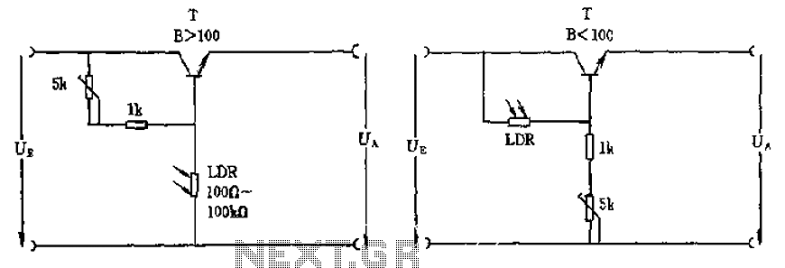
The circuit depicted involves a photoresistor (LDR) connected to a transistor, which operates at either a high or low level based on light conditions. The amplification factor of the transistor is 100, which is adequate for the application. The...
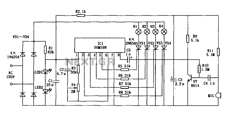
Family karaoke lighting design incorporates various methods for circuit control. The control circuit described here features a four-way light output with loop jumping and speed control capabilities. A microphone detects the acoustic signal strength, allowing the lights to jump...
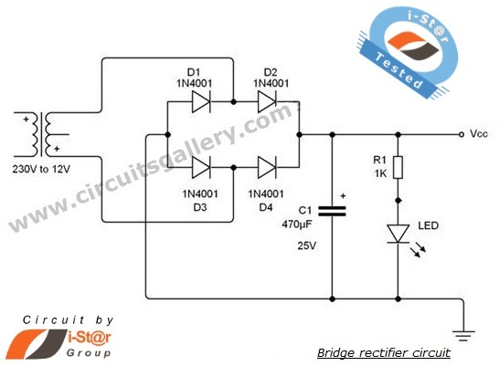
A rectifier is an electronic circuit that converts AC voltage to DC voltage. It can be implemented using a combination of capacitors and diodes. The unique property of diodes, which allows current to flow in a single direction, is...
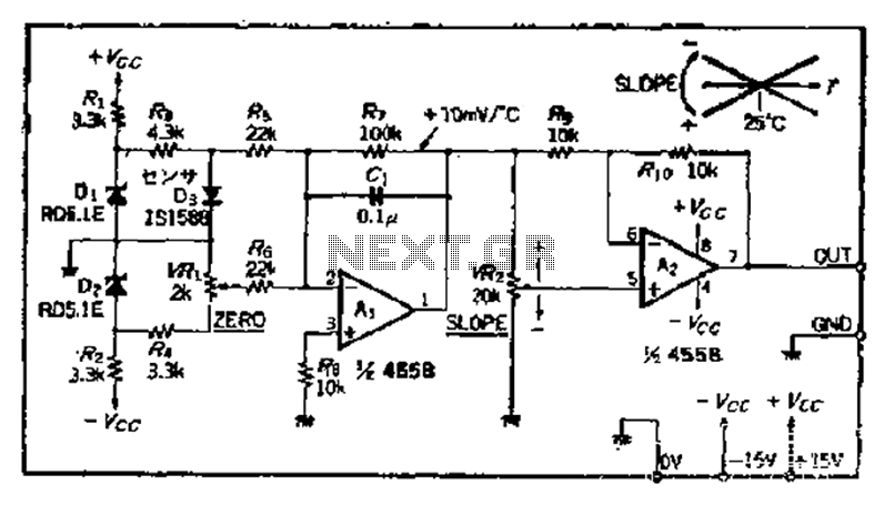
A temperature sensor can be created using a standard silicon diode, which produces approximately 2.2 mV per degree Celsius variation. An operational amplifier (OP amplifier) is utilized with a positive reference temperature (room temperature). The output signal is amplified...