
It can produce 10mV- compensation voltage temperature compensation voltage generating circuit

The described temperature sensor circuit employs a silicon diode as the sensing element, leveraging its forward voltage drop characteristics that vary with temperature. When the diode is forward-biased, it generates a small voltage that correlates with temperature changes. The output from the diode is fed into an operational amplifier configured in a non-inverting configuration to amplify the small signal generated by the diode.
The operational amplifier is set with a gain of five, achieved through a feedback resistor network. This amplification is essential to make the small voltage variations detectable and usable for further processing. The output of the operational amplifier provides a linear representation of temperature changes, producing a signal of +10 mV per degree Celsius.
To allow for versatility in the application, a variable resistor is integrated into the circuit. This resistor enables adjustments to the gain and polarity of the output signal. By altering the resistance, the user can modify the amplification factor, thereby tailoring the sensor's response to specific requirements. Furthermore, the circuit is designed to accommodate both positive and negative temperature coefficients, enabling it to output voltages ranging from +10 mV to -10 mV. This feature is particularly useful for applications where temperature may fluctuate above and below a reference point, such as in environmental monitoring systems or HVAC controls.
The overall design is compact and efficient, making it suitable for various electronic applications where precise temperature measurement and control are essential. The simplicity of the silicon diode as a sensor combined with the flexibility offered by the operational amplifier and variable resistor makes this circuit a practical solution for temperature sensing needs.A temperature sensor such as the use of ordinary silicon diode, about one obtained 2.2mV ,/variation of Oc. OP amplifier AL with the positive reference temperature (room ju) un der. Sound extravagant drop to zero, only the changed portion magnified about 5 times to obtain a + 10mV/port C output - OP amplifier Az is a random variable resistor for changing the gain and polarity. The - circuit, can be generated from the positive to the negative temperature coefficient of any voltage (+ 10mV ~ -lOmV) O
Related Circuits
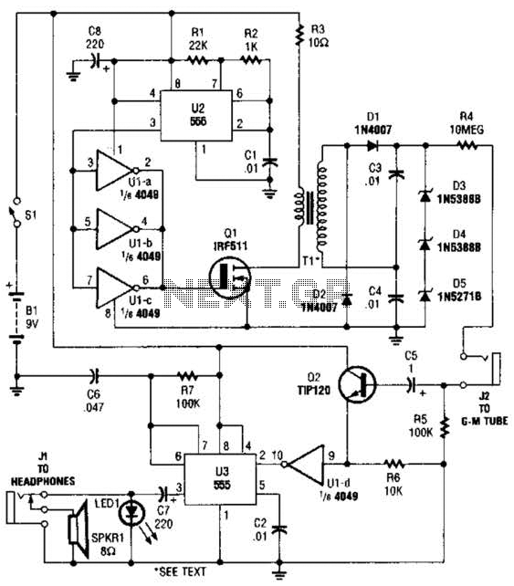
The circuit is constructed using a 4049 hex inverter (U1), two 555 oscillator/timers (U2 and U3), two transistors, a Geiger-Muller tube, and several additional support components. The first 555 timer (U2) is set up for astable operation. The output...

This project is designed to program the 8-pin PIC12c508A and 18-pin PIC16F84 microcontroller chips to support the projects we have designed; however, it will also program a number of other 8-pin and 18-pin microcontrollers, and the full list can...

The PM4040F is utilized in switching power supply applications for medium power ranges. It is designed to drive power supplies between 200W and 800W, as illustrated in the accompanying bridge circuit. For power applications below 1000W, an alternative circuit...

A DS18S20-based serial port temperature sensor has been developed for connection to the USB port of an Asus WL-500gp v2. The temperature sensor functions correctly when directly connected to a PC's serial port; however, issues arise when attempting to...
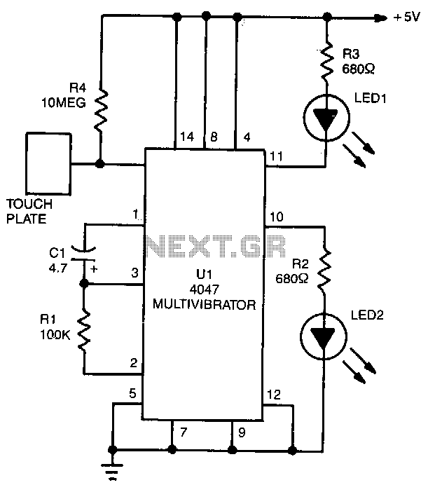
LED1 and LED2 indicators activate and stay illuminated each time the circuit is triggered. During the timing cycle, the Q output at pin 10 of U1 becomes positive when the Q output at pin 11 turns negative. The two...
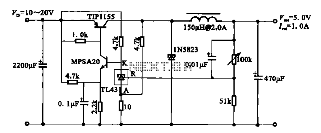
The 5V regulator circuit is designed to convert a DC input voltage ranging from 10V to 20V into a stable 5V output. This circuit features low power consumption and high efficiency. The 5V regulator circuit typically employs a linear voltage...