
Audio / Video Distribution Amplifier


The circuit described is an audio and video gain control amplifier designed to enhance signal quality when duplicating video tapes. It is particularly useful in home entertainment systems where multiple devices may require signal adjustments to maintain optimal performance. The circuit utilizes an integrated circuit (IC) as the core amplification component, which simplifies the design and reduces the number of discrete components needed.
The primary function of this circuit is to adjust the gain of both audio and video signals. This is essential when copying video tapes, as the audio quality often degrades during the duplication process. By fine-tuning the gain, the circuit ensures that the output signals maintain their integrity, preventing issues such as distortion or loss of clarity.
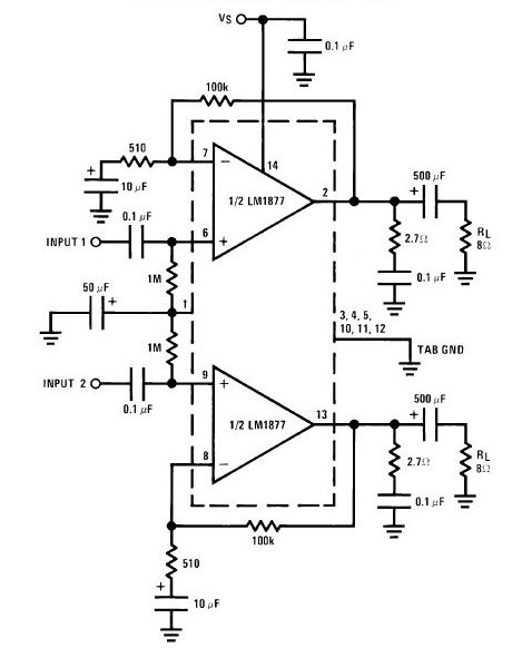
In terms of design, the circuit operates using a standard amplifier configuration. The audio amplifier is built around a specific operational amplifier (IC1), with the second channel mirroring the first. The inputs for the audio signal are connected to pins 5 and 6 of the operational amplifier, while pin 7 serves as the output. This configuration allows for independent control of each channel, enabling precise adjustments to both audio and video signals.
To implement this circuit, it is important to consider the power supply requirements and ensure that the operational amplifier is operating within its specified voltage range. Additionally, appropriate filtering capacitors should be included to minimize noise and stabilize the power supply to the amplifier. The overall design should also account for impedance matching to prevent signal loss and ensure compatibility with other devices in the home entertainment system.
In conclusion, this circuit serves as a valuable tool for enhancing audio and video signals in home entertainment applications, particularly in scenarios involving tape duplication. Its straightforward design and effective gain control capabilities make it an essential component for anyone looking to improve their audio-visual experience.With the amount of equipment in home entertainment centers today the need to be able to vary the gain of the audio or video signal is needed. I found this particular circuit helpful when used in conjunction with the Universal Descrambler and a Stabilizer circuit I built for making copies of video tapes.
It not only allowed me the ability to fine tune the video strength it also helped me increase the recorded audio which typically becomes poor when making tape copies. Circuit operation is straight forward for amplifier circuits. The second channel for the audio amplifier is made up of the same components except the other half of IC1 is used.
Pin 6 & 5 are inputs and 7 is the output. 🔗 External reference
Related Circuits
The LA4440 is a dual-channel audio power amplifier integrated circuit (IC) designed for stereo and bridge amplifier applications. In dual mode, it provides significant audio amplification for various audio systems. The LA4440 audio power amplifier is engineered to deliver high-quality...
Circuit stereo TDA2822 audio power amplifier circuit schematics. In this series, the TDA2822M IC is utilized as the primary amplifier. Additionally, alternatives such as KA2209 and NJM2073 can also be employed. The TDA2822 audio power amplifier circuit is designed to...
Read the generic sound level from an electret microphone. Several schematics utilize NPN transistors that yield an inverted output (~5V when quiet, ~0V when loud, with linear operation in between). However, a non-inverted output is desired, where a super...
The 25-watt audio amplifier circuit is powered by a tube circuit. The tube transistor (TR) will amplify the input to approximately 20 watts, while a dual transformer can increase the output to 40 watts. A wide voltage range of...
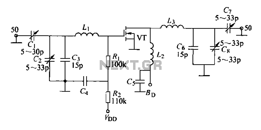
A 175 MHz high-frequency amplifier circuit utilizing a field-effect transistor (FET) is presented. The field-effect transistor used is the 3D04H, along with its associated components and parameters. The 175 MHz high-frequency amplifier circuit is designed to amplify signals in the...

This integrated circuit (IC) chip is specifically designed for power boosting applications in automobiles. It features self-protection mechanisms against short circuits and thermal issues. In the bridge configuration depicted, it can deliver 20 watts of power to a 2-ohm...