
Audio/Video Switcher
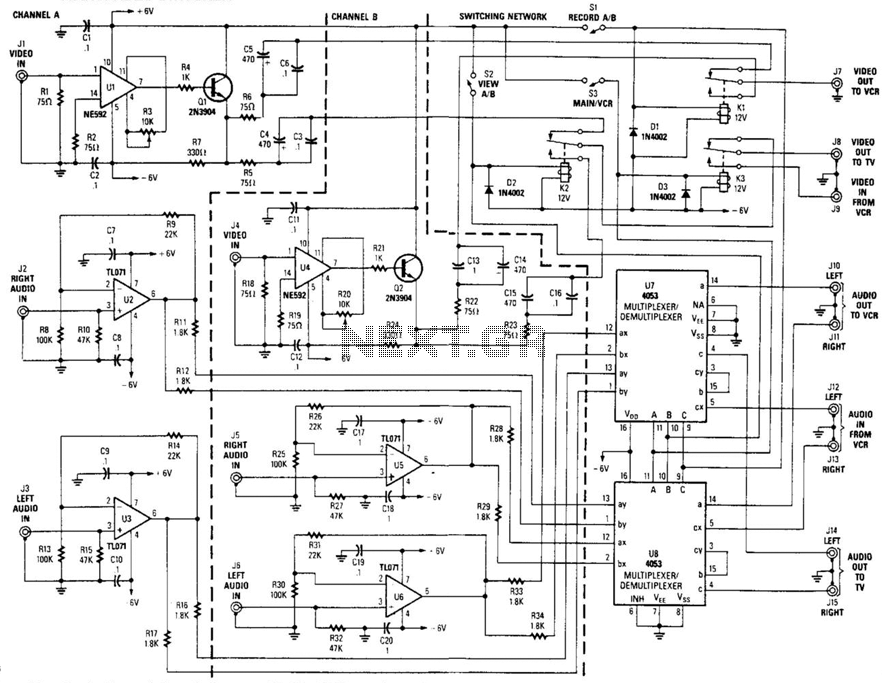
This circuit functions as a two-channel baseband video switcher, designed to manage video and audio signals efficiently. The core of the circuit involves buffer amplifiers U1/Q1 and U4/Q4, which are responsible for producing a buffered 75-ohm video signal. This specification is critical for maintaining signal integrity over standard video transmission lines.
The switching mechanism is facilitated by the relay network composed of K1, K2, and K3. Relay K1 plays a pivotal role by selecting one of the two video amplifiers, directing the output to connector J7. This feature allows for seamless switching between video sources without degradation of the signal. Following this, relay K2 routes the output from the selected video amplifier to K3. K3 further processes the signal, allowing it to be output to either J8 or to connect J9 with J8, thereby providing flexibility in video output options.
In addition to video switching, the circuit incorporates audio amplification through U2 and J3. These components drive the CD4053 analog switches (U7 and J8), which are utilized to route audio signals. The audio inputs from connectors J1 and J2 can be directed to either J14/J15 or J10/J11, enhancing the circuit's versatility. Furthermore, audio inputs from J12 and J13 can also be routed to the same output jacks, allowing for multiple audio sources to be managed effectively.
Overall, this circuit design illustrates a well-integrated approach to managing both video and audio signals, making it suitable for applications requiring reliable switching capabilities in multimedia environments. This circuit is a two-channel baseband video switcher. Buffer amps Ul/Ql, U4/Q4, and associated components produce a b uffered 75- video signal, which is routed to switching network K1/K2/K3. Relay K1 selects either of these two video amplifiers and feeds J7. K2 also routes the output of either video amplifier to K3, which passes the selected video channel to J8 or connects J9 to J8. U2 and J3 are audio amplifiers, which drive U7 and J8 (CD4053 analog switches) to route audio from J1 and J2 to either J14/J15, or J10/J11.
Also, audio from J12/J13 can be routed to these jacks. 🔗 External reference
Related Circuits
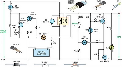
This circuit is designed to switch power to a Peltier cooler in a vehicle. Power is supplied to the load from the vehicle's battery when the ignition switch is on and from an SLA auxiliary battery when the ignition...
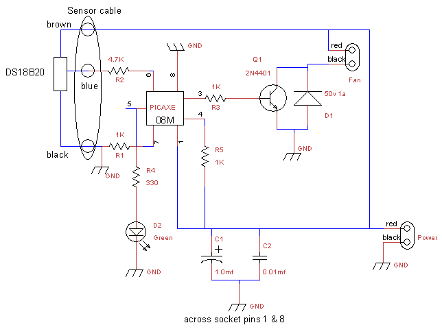
This is a fan controller designed for an audio/video cabinet. It utilizes a PICAXE 08M microcontroller and a DS18B20 temperature sensor. The fan activates at 30 degrees Celsius (approximately 86 degrees Fahrenheit) and deactivates at 28 degrees Celsius (around...
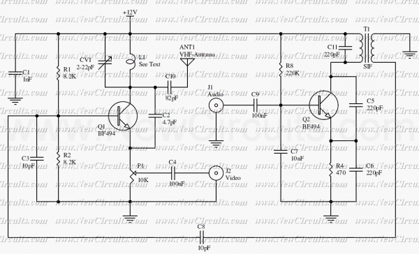
The circuit presented here is a simple audio/video transmitter with a range of 3 to 5 metres. The A/V signal source for the circuit may be a VCR, a satellite receiver or a video game etc. A mixer which...
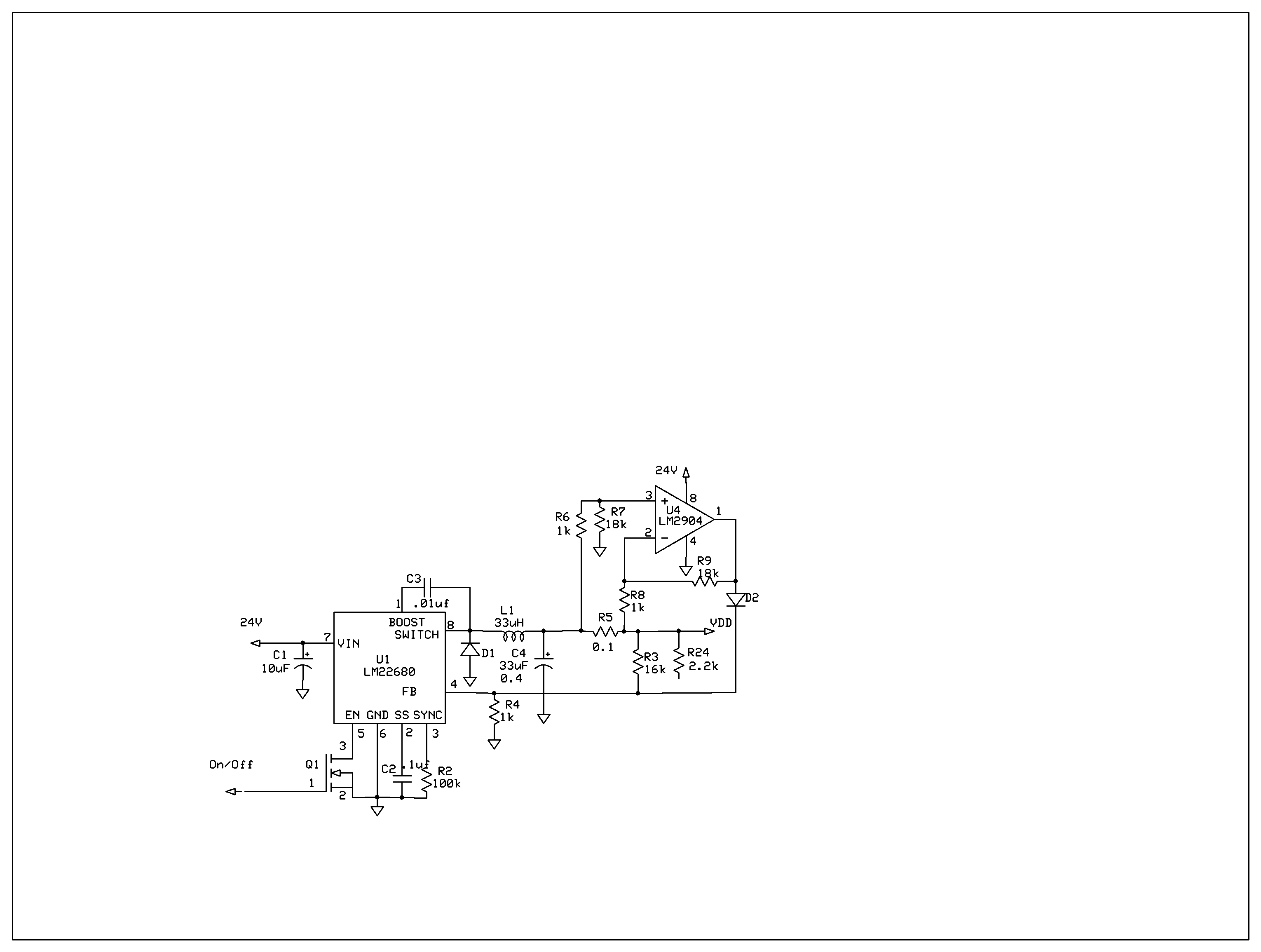
The product requires a voltage-controlled, current-limited power supply. Various switcher chips have been used with an op-amp to provide feedback for a current sense voltage to the feedback pin. Currently, an LM22680 is in use, but it has shown...
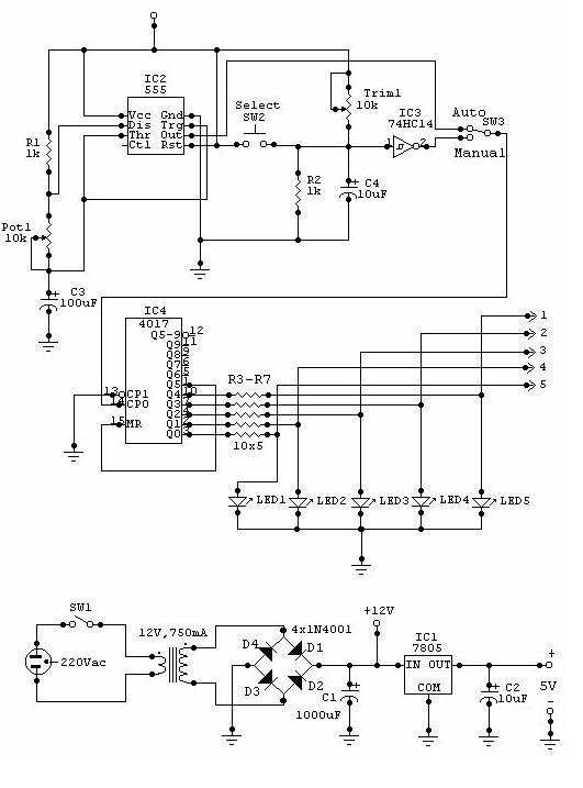
This circuit can be utilized for multiple cameras with a single monitor. The operation can be manual or automatic. In automatic mode, the switch... This circuit is designed to enable the connection of multiple cameras to a single monitor, allowing...
As with the Electronic sel. 8 we also have here a circuit with a choice of 8 different sources. The difference is that only two of the switches are used and the movement of commands is Up-Down in series....
Warning: include(partials/cookie-banner.php): Failed to open stream: Permission denied in /var/www/html/nextgr/view-circuit.php on line 713
Warning: include(): Failed opening 'partials/cookie-banner.php' for inclusion (include_path='.:/usr/share/php') in /var/www/html/nextgr/view-circuit.php on line 713