
8 way Up/Down Switcher

The described circuit functions as an 8-source selector, allowing for the selection of one of eight different audio or signal sources. The control mechanism utilizes a series of push-button switches (S1 and S2) that facilitate an Up-Down command sequence to navigate through the selection. The circuit includes visual indicators in the form of LEDs (D1-D8), which illuminate to indicate the active source.
For the relay control, the SL1 connector is employed to activate a relay circuit, enabling the selection of the active source through relay switching. An alternative configuration utilizes the 74HC4051 integrated circuit (IC3), which serves as an 8-channel analog multiplexer. This allows for the selection of one of eight different input signals without the need for mechanical relays, enhancing reliability and reducing mechanical wear.
In stereo applications, it is necessary to implement two 74HC4051 ICs, one for each audio channel, ensuring that both left and right channels can independently select from the same eight sources. To achieve an electronic variable resistor functionality, a specific arrangement of resistors (R1-R8) is required before the 74HC4051, enabling the circuit to function as a programmable attenuator with eight distinct steps.
The selection of components includes resistors with values such as 10 kΩ (R1, R2, R9), 100 kΩ (R3, R4, R5, R6, R7, R8), and a 470 Ω resistor (R10) to limit LED current. Capacitors are specified as 100 nF (C1, C2), 47 nF (C3, C4, C7), and 10 µF (C5, C6) for filtering and stability. The additional integration of a 74HC237 (IC4) allows for decoding functions, while the 4584 (IC1) and 74HC193 (IC2) provide further logic and control capabilities, enhancing the overall functionality of the circuit.
This circuit design is suitable for various applications that require source selection and can be adapted for use in audio systems, testing equipment, or any scenario where multiple signal sources need to be managed efficiently.As with the Electronic sel. 8 we also have here a circuit with a choice of 8 different sources. The difference is that only two of the switches are used and the movement of commands is Up-Down in series. We have evidence of activity at each entrance by the corresponding Led 1-8. Throw the SL1 connector, we drive the Relay of the circuit Relay Sel. 8. Alternately we can use the IC3, which is a 8-channel multiplexer analog choices, without relay. For stereo use, we must use two IC3, one for each channel. If we place the correct [pairing] combination resistors before the IC3, the circuit becomes an electronic variable resistor with 8 steps.
Parts: R1-2=10Kohms C3-4=47nF63V MKT IC3=74HC4051 Single 8-Ch. Analog [Comp. 4051] R3-4=100Kohms C5-6=10uF16V IC4=74HC237 R5-8=100Kohms C7=47nF63V MKT S1-2=Push Button sw R9=10Kohms .D1-8=Led 3mm. S3=DIL 8P SW R10=470 ohms IC1=4584 C1-2=100nF63V MKT IC2=74HC193 🔗 External reference
Related Circuits
This circuit can be used for multiple cameras with one monitor. The circuit can be operated manually or automatically. The described circuit functions as a video switching system, enabling the connection of multiple camera inputs to a single monitor output....
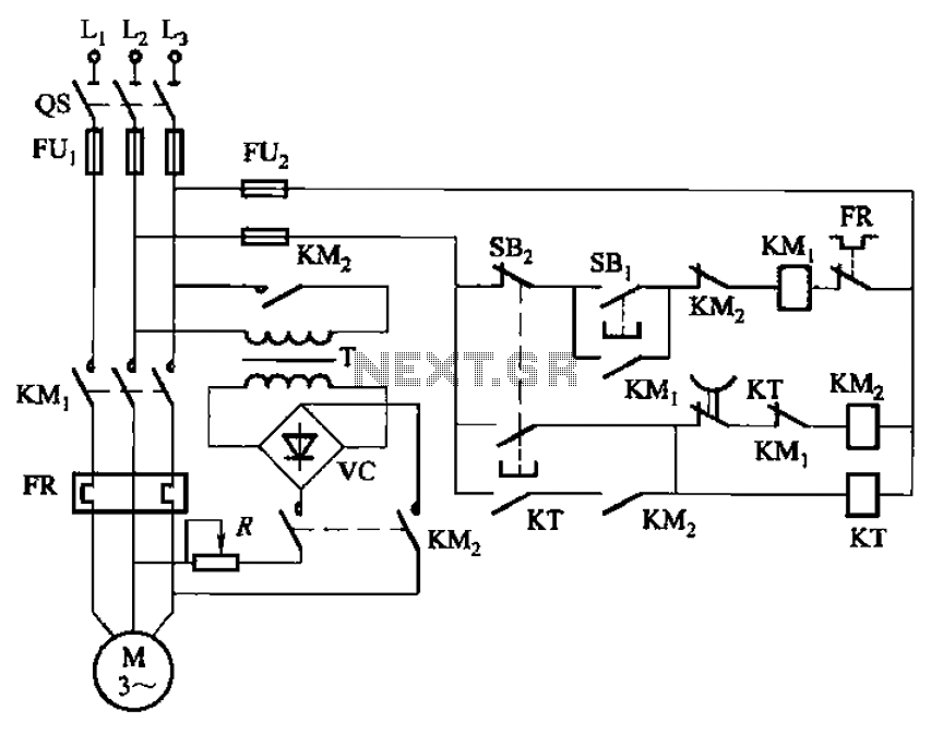
The circuit depicted in Figure 3-135 employs a time relay (KT) to determine the braking time. The circuit utilizes a time relay, which is a crucial component for controlling the duration of the braking process. The time relay KT is...
This project consists of two circuits on two separate boards. The initial circuit is built around a PIC16F628A microcontroller. It was constructed on an experimental PC board utilizing surface-mount components and was completed in under one hour, with an...
The protected section of track can be of any desired length and does not need to be equal on both sides of the crossing. The circuit operates bidirectionally and can be linked with other grade crossing circuits to provide...
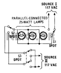
This hookup is useful in certain house wiring situations where only two wires are available between switches, rather than the usual three-way setup that requires three wires. SI and S2 are standard three-way switches, while S3, a double-pole double-throw...
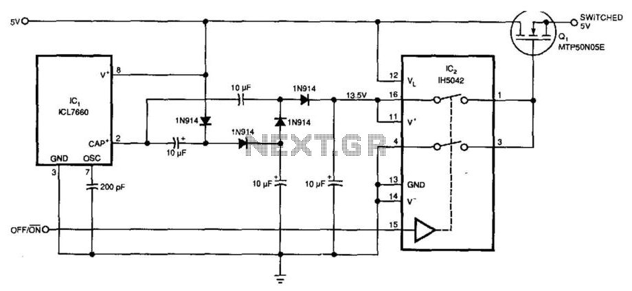
Requiring only 10 µA of quiescent current, the circuit produces an ON-resistance of only 0.1 ohm. IC1 serves as a charge pump voltage converter to generate a 5V level, allowing analog switch IC2 to provide a 10V swing to...