
Camera Switcher

This circuit is designed to enable the connection of multiple cameras to a single monitor, allowing for versatile surveillance or monitoring applications. The system can be toggled between manual and automatic operation modes, providing flexibility based on user needs.
In manual mode, the user can select which camera's feed is displayed on the monitor using a physical switch or button. This allows for direct control over the viewing source, making it suitable for scenarios where specific monitoring is required at any given time.
In automatic mode, the circuit incorporates a switching mechanism that cycles through the camera feeds at predetermined intervals. This can be achieved using a microcontroller or a timer circuit that activates each camera in succession. The automatic operation can be beneficial for applications such as security surveillance, where continuous monitoring of multiple areas is necessary without the need for constant user interaction.
The circuit may include additional features such as indicators to show which camera is currently active and a user interface for adjusting the timing of the automatic switching. Power management components should also be considered to ensure that the circuit operates efficiently without overloading the power supply.
Overall, this multi-camera monitoring circuit is a practical solution for environments requiring comprehensive surveillance coverage, balancing user control with automated functionality.This circuit can be used for multiple cameras with one monitor. The circuit can be operated manually or automatically. When operated automatically the swi.. 🔗 External reference
Related Circuits
This project is a fun and safe activity for individuals interested in magnetically launching projectiles. The operation involves placing a ferromagnetic projectile at one end of a coil and applying a power pulse. The key is to turn off...
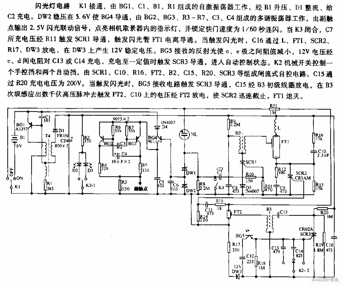
The camera flashlight circuit activates when switch K1 is engaged. This triggers a self-oscillating circuit consisting of BG1, capacitor C1, battery B1, and resistor R1. Once operational, the circuit boosts the voltage through B1 and rectifies it using diode...
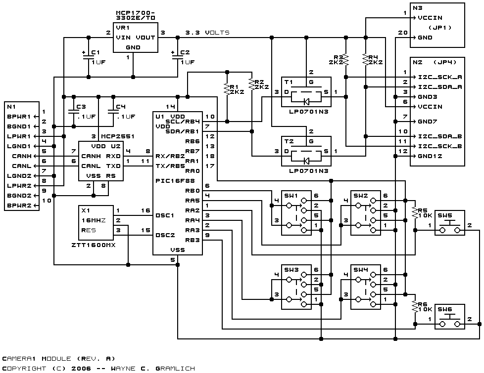
The Camera1 module provides a RoboBricks2 bus interface for a General-Vision Cognisight MTVS vision system. This module includes a built-in camera and electronics for recognizing features in an image. The recognition hardware is based on neural network technology. Initially,...
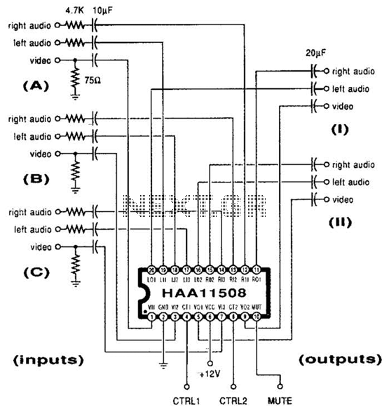
This channel selector selects video and stereo audio from any one of three different sources. The circuit should be constructed on a PC board with plenty of ground plane to minimize noise. The channel selector circuit is designed to facilitate...
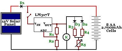
The circuit is designed to power a CCTV camera, provide lighting inside a nestbox, and charge batteries using a photovoltaic (PV) solar panel. It includes a circuit diagram for a solar-powered wireless CCTV camera with battery backup. D1 is...
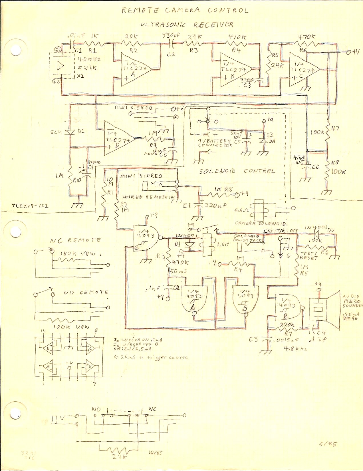
A camera trigger designed to capture transient phenomena was created using a Mamiya ZE 35mm camera and a Mamiyalite ZE flash unit. At that time, the only method for remotely triggering the camera was through the cable release socket...