
Audio Visual Ringer

The Audio Visual Ringer circuit is designed to provide a visual and auditory indication of incoming telephone calls, particularly in situations where the primary ringer may not be easily heard. This circuit typically includes a sound-generating component, such as a piezoelectric buzzer or speaker, which produces an audible alert when a call is received. Additionally, a visual indicator, such as an LED or a series of LEDs, can be employed to provide a visual cue.
The circuit operates by detecting the ringing signal from the telephone line. This is accomplished using a transformer or a dedicated ringing signal detector that isolates the ringing voltage from the phone line. When the incoming call signal is detected, the circuit activates both the audio and visual indicators.
For the audio component, the output from the transformer can be fed into a simple amplifier circuit to boost the sound level, ensuring that it is audible even in noisy environments. The visual component can be configured to flash in sync with the ringing signal, providing a clear indication of an incoming call.
Power for the Audio Visual Ringer can be supplied from a standard AC outlet or a low-voltage DC source, depending on the design. Proper isolation and safety measures should be implemented to prevent any electrical hazards, especially when interfacing with the telephone line.
This circuit is particularly useful in large homes, offices, or environments where the primary telephone ringer may be out of earshot, ensuring that incoming calls are effectively communicated to users in adjacent areas.Audio Visual Ringer. Many a times one needs an extra telephone ringer in an ad-joining room to know if there is an incoming call. For example, if the telephone is installed in. 🔗 External reference
Related Circuits
The following schematic illustrates a 5.8W stereo power amplifier utilizing the Samsung IC KA2211. Each channel delivers a power output of 5.8W, resulting in a maximum combined output of 2 x 5.8W. The KA2211 is a dual audio power...
This audio mixer circuit does not utilize a low impedance input to mix non-ideal sources; instead, it employs multiple amplifiers to provide ideal sources prior to mixing through simple resistors. An ideal source is characterized by low impedances, which...
High-end audio equipment is typically controlled digitally by a microprocessor (microcontroller) system. It is necessary to have a digital interface that allows for effective communication and control. High-end audio systems utilize a microcontroller to manage various functionalities, enabling precise control...
What is so special? First of all, it has a very low harmonic distortion. Typically, manufacturers indicate the maximum power of their products with a harmonic content of 10%. In contrast, this chip achieves a harmonic distortion of only...
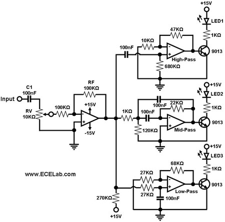
Figure 1 illustrates a simple circuit designed for converting an audio signal (such as one from the output terminals of a CD player). The circuit primarily consists of a buffer/amplifier stage and three filtering circuits: a high-pass filter, a...
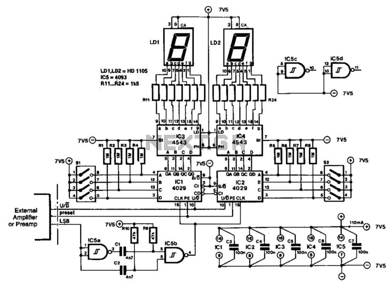
The indicator is designed for use with an audio amplifier or preamplifier, but it can also be utilized in other applications requiring rapid counting of steps or changes. To avoid interference with the audio signal, the circuit operates in...