
KA2211 5.8W Stereo Audio Amplifier

The schematic for the 5.8W stereo power amplifier features the KA2211 integrated circuit, which is designed for driving speakers in consumer audio applications. This amplifier is capable of delivering a total output of 11.6W when both channels are utilized to their maximum capacity. The KA2211 operates with a supply voltage typically in the range of 12V to 24V, allowing for flexibility in power supply design.
The input stage of the amplifier circuit is configured to accept audio signals from various sources, such as smartphones, computers, or other audio devices. Capacitors are used at the input to block any DC offset, ensuring that only the AC audio signal is amplified.
The KA2211 features built-in short-circuit protection and thermal overload protection, enhancing the reliability of the amplifier in various operating conditions. The output stage is designed to drive low-impedance loads, making it suitable for use with standard speakers.
For optimal performance, the circuit includes feedback components that stabilize gain and reduce distortion, ensuring high-quality audio output. Additionally, bypass capacitors are placed near the power supply pins of the KA2211 to filter out any noise and provide a stable voltage to the amplifier.
Overall, the 5.8W stereo power amplifier schematic using the KA2211 is a robust solution for compact audio amplification needs, suitable for a range of applications from portable speakers to home audio systems.The following schematic is the diagram of 5.8 stereo power amplifier based on Samsung IC KA2211. The 5.8W is the power output on each channel, it means that the output will be 2 x 5.8W (maximum). About KA2211: KA2211 is a dual audio power am.. 🔗 External reference
Related Circuits
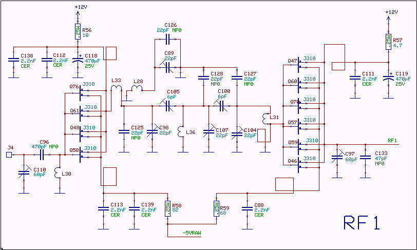
The RF amplifiers utilize noiseless feedback through the drain-gate capacitance, incorporating an inductor in the source lead to achieve the necessary 90-degree phase shift between the gate voltage and channel current. The first RF amplifier provides approximately 4 dB...
A power amplifier was constructed during secondary school using transistors. The circuit offered limited power and featured a poorly designed PCB. Concurrently, access to the TDA1524 datasheet, a tone and volume control circuit, led to the decision to create...
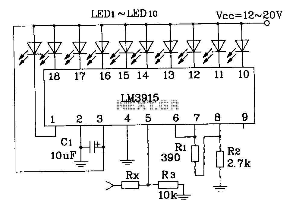
This document describes a simple LM3915 audio power meter circuit diagram. It notes that if the internal resistance of the speaker is 4 ohms, a resistor value of 10k ohms should be used for Rx. For an 8-ohm speaker,...
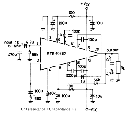
Using the STK4038X audio amplifier IC, can be designed a very simple high power and efficiency audio power amplifier. This circuit is manufactured by Sanyo Corporation and will provide an output power of 60 watts on an 8 ohms...
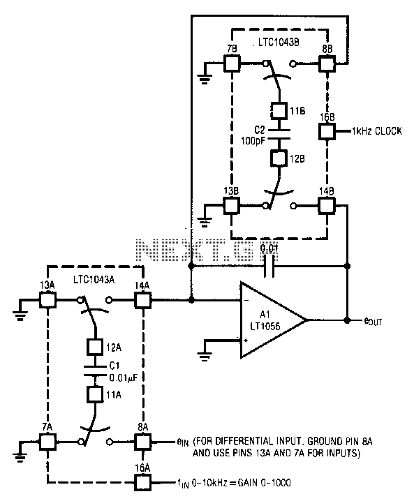
The circuit utilizes the LTC1043 in a variable gain amplifier configuration, which offers continuously adjustable gain, gain stability of 20 ppm/°C, and supports both single-ended and differential inputs. Two separate LTC1043 devices are employed in the design. The LTC1043B...
This compound series-feedback circuit provides high input impedance and stable wide-band gain for general-purpose video amplifier applications. The compound series-feedback circuit is designed to achieve high input impedance, which is essential for minimizing loading effects on the preceding stage of...