
Audio Wattmeter Circuit with LM3915

The sound wattmeter circuit is built around the LM3915 LED bar graph/LED dot display driver, which is capable of driving up to 10 LEDs in a linear fashion. The circuit can be powered by a DC adapter providing between 12 to 20 volts, ensuring that the LED display is adequately illuminated for clear visibility. The use of colored LEDs allows for a straightforward interpretation of power levels, with different colors representing different ranges of output power.
The resistance value R1 is critical as it determines the sensitivity of the wattmeter based on the speaker impedance. The accompanying table provides specific resistance values tailored for common speaker impedances, such as 4 ohms and 8 ohms. This ensures accurate readings of power output relative to the connected speaker.
The circuit’s design accommodates the positive swing of the audio signal, which is sufficient for most amplifier testing purposes. The sine wave input, commonly used in audio testing, allows for a consistent representation of power output. Additionally, for scenarios where an actual speaker is not available, the option to connect a dummy load resistor provides flexibility in testing the wattmeter’s functionality without compromising accuracy.
In summary, this sound wattmeter circuit is a practical tool for audio engineers and enthusiasts, offering a simple yet effective means of measuring amplifier power output through a visual LED display. Its ease of integration and adaptability to different speaker impedances make it a valuable addition to any audio testing setup.This sound wattmeter uses a row of colored LEDs as a scale to show the relative power output of your amplifier in watts. It is easy to be inserted into the speaker box. All you need is to hook a supply voltage to it. The value of R1 depends upon the impedance of the speaker being used. The table near the sound wattmeter diagram shows the necessary values of R1. The supply voltage of the circuit is 12 20 volts/50 mA DC adapter. Take note that the LM3915 indicates only the positive swing of the signal. Anyway, by testing amplifiers it does not matter anyhow since a sine wave is normally used as a test signal. To test the circuit without using an actual speaker, you can connect a dummy resistor with a value of either 8 or 4 ohms.
🔗 External reference
Related Circuits
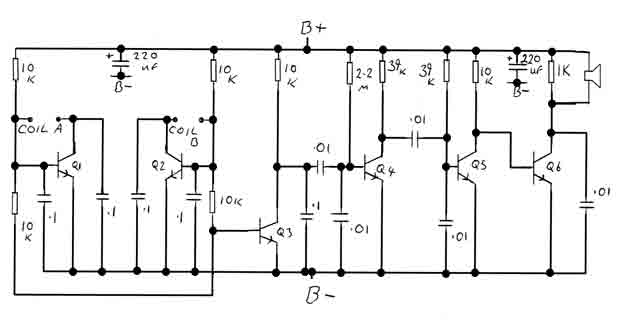
By adjusting the oscillators so their frequencies are very nearly the same, the difference between them is made audible as a beat note. This beat note changes slightly when the search loop is moved over or near to a...
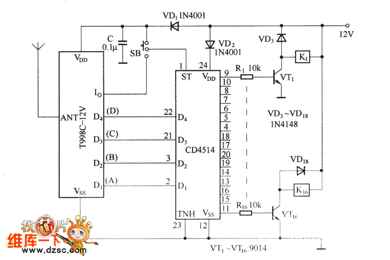
The circuit functions as both a latch output and a non-latched output. The control switch, labeled SB, governs the operation. When both SB and VDD are activated, the circuit enters the latch output state, allowing the sixteen output terminals...
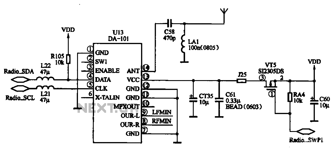
FM radio chip circuits operate differently, as illustrated by the DA-101 chip FM radio circuit. In this configuration, the FM radio broadcast program is received through the headset jack, which functions as an antenna. The signal captured by the...
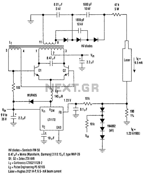
Driving Helium-Neon lasers can be greatly simplified using this power supply configuration. When power is applied, the laser does not conduct, and the voltage across the 190-ohm resistor is zero. However, a resonant circuit and a voltage tripler then...
Utilize a pair of Maxim's 5V-powered MAX231 RS-232C transmitters as drivers to achieve a dual-color LED. These transmitters necessitate only a single-ended, 5-V input to internally generate ±10 V. Their outputs are designed to be short-circuit-proof and can provide...
The high durability of a light-emitting diode (LED) makes it suitable for ON/OFF indicator applications. However, there are limitations regarding low operating voltage. Light-emitting diodes (LEDs) are semiconductor devices that emit light when an electric current passes through them. Their...