
40kHZ ultrasonic transmitter circuit diagram

The ultrasonic transmitter circuit operates at a frequency of 40 kHz, which is within the ultrasonic range, allowing for various applications such as distance measurement, object detection, and communication. The core of the circuit is the LM555 timer configured in astable mode to generate a continuous square wave output. The frequency of oscillation can be adjusted by varying the resistance of the potentiometer RP, which affects the timing capacitors and resistors in the circuit.
The LM555 output drives the ultrasonic transducer T40-16, which converts the electrical signals into ultrasonic sound waves. This transducer is specifically designed for ultrasonic applications, ensuring efficient conversion and transmission of the generated signals. The circuit is powered by a 9V supply, which is common for low-power electronic devices, ensuring ease of integration into various systems.
The current consumption of 40 to 50 mA indicates that the circuit is designed for low power applications, making it suitable for battery-operated devices. The ability to transmit ultrasonic signals over distances greater than 8 meters enhances its utility in various scenarios, such as in robotics for obstacle avoidance or in industrial applications for non-destructive testing.
In terms of component selection, the LM555 timer is a versatile and widely used component in timer, delay, pulse generation, and oscillator applications. The availability of the NE555 as a direct replacement ensures that the circuit can be easily maintained or modified without compromising performance. Overall, this ultrasonic transmitter circuit exemplifies simplicity and effectiveness in generating ultrasonic signals for a range of applications.40kHZ ultrasonic transmitter circuit of five, by the time base circuit LM555 and the external components 40kHZ multivibrator circuit, the resistance adjusting resistor RP can c hange the oscillation frequency. 3 feet from the LM555 output drives ultrasonic transducer T40-16, so as to emit ultrasonic signals. Circuit is simple and easy system. Circuit voltage of 9V, working current 40 ~ 50mA. Transmitting ultrasonic signals greater than 8m. LM555 NE555 direct replacement available, the effect is the same.
Related Circuits
Typically, when a car door is closed, the dome light turns off immediately. This circuit allows the dome light to gradually fade in brightness before eventually turning off. An electronic transformer dims halogen lamps and is a straightforward device...
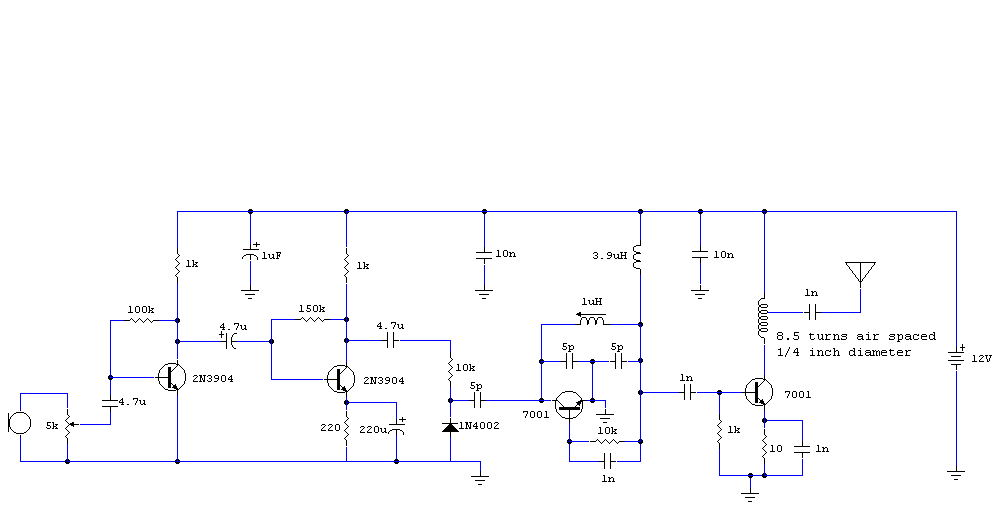
The audio circuit described is a microphone utilizing two 2N3904 transistors as the audio preamplifier. The audio/microphone gain is adjustable via a 5k preset potentiometer. The circuit employs a Colpitts oscillator for frequency generation, which is free-running and operates...
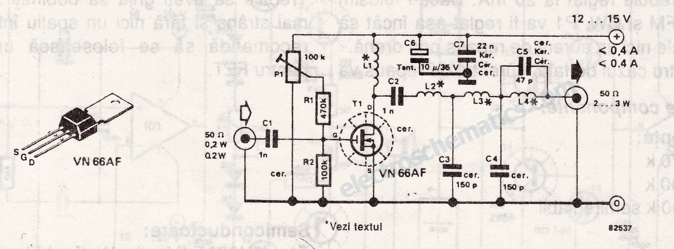
The 10-meter 27MHz continuous wave (CW) radio amplifier is equipped with the VN66AF transistor produced by Siliconix, which offers several advantages: it is inexpensive, provides excellent dielectric insulation, and has high gain. The VN66AF is utilized as an RF...
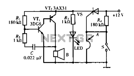
The circuit operates based on a principle where the SCR (Silicon Controlled Rectifier) trigger is grounded, keeping it in the off state. When a burglar triggers the alarm, a voltage is supplied to the SCR trigger, turning it on....
This is a 25-watt basic power amplifier designed for ease of construction at a reasonable cost. It offers superior performance compared to standard STK module amplifiers commonly found in most mass-market stereo receivers produced today. The 25-watt basic power amplifier...

This is an economical FM booster circuit designed to enhance the reception of distant FM stations on local radios. The circuit diagram features a common-emitter tuned RF preamplifier utilizing the VHF/UHF transistor 2SC2570. The circuit's output should be directly...