
Echo Depth Sounding Sonar for Boats
The typical configuration of the electronic sonar includes an ultrasonic transmitter that emits a short pulse in the range of 150-200 kHz. This pulse reflects off the seabed, and the echo is captured by the hydrophone, which converts it into an electrical signal. This signal is used to illuminate a neon light that moves at a fixed frequency on a calibrated disk, indicating the measured depth. The calibration allows for direct reading of depth, and experienced mariners can infer seabed type based on the light's behavior—brief flashes for sandy bottoms, longer flashes for rocky bottoms, and prolonged blinking for softer substrates.
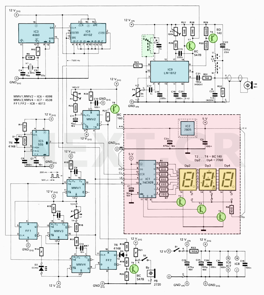
The construction of this sonar system features a digital display that, while lacking detailed seabed information, provides more precise depth readings. The sonar circuit is straightforward to build, with the transmitter and hydrophone housed together. The transceiver connects to IC9 (LM 1812 from National Semiconductor).
The ultrasonic pulse travels twice the distance of the water depth. Given that sound travels in water at an average speed of 1500 m/s (at 20°C with a 2% salt content), a depth of 7.5 meters corresponds to a round-trip time of 10 ms. If the timer frequency of IC1 is set to 750 Hz and pulse arrivals are recorded at 10 ms, the display will read 7 m. For greater accuracy, the clock frequency can be increased to 7500 Hz, allowing depth readings to be accurate to the nearest tenth of a meter.
The display, memory, and imaging drive are integrated within IC1. Upon receiving echoes, IC9 sends a stop pulse to the display, which then stores the information in memory before displaying it on seven-segment LEDs. A new measurement cycle begins with a zero-cycle pulse generated by IC5 every 200 ms, allowing for depth measurements of up to 150 meters. The reset signal also initiates pulse transmission and activates an alarm via MMV4 and FF2, which indicates a "shallow" condition if the output of MMV4 is high during echo detection. The alarm threshold can be adjusted using P1, ranging from 1 m to 10 m.
Monostable MMV3 disables the display when no echo is detected for a specified time set by P2. When an echo is received, LED D2 blinks to indicate activity. IC9, the heart of the device, activates the built-in modulator at pin 8 to generate the ultrasound pulse at 200 kHz. The modulator and the second high-frequency amplifier share the tuned circuit L1/C14, ensuring synchronized frequencies for both transmission and reception.
The output stage amplifies the 200 kHz pulse and drives the ultrasonic transmitter through a transistor driver (T8) and coil (L2), which forms a tuned circuit with distributed capacitance and C22. Between transmission pulses, echoes are detected and processed through high-frequency amplifiers, with noise pulses filtered out using a combination of a pulse repeater and integrator detector.
The construction and assembly of the sonar system require careful positioning of the transmit/receive element, ideally perpendicular to the vessel's axis. The element may need to be housed in an adapter box, and if the hull is fiberglass, it can be placed inside. The connection cable should be kept separate from other cables to avoid noise interference. Various transducers are suitable for this application, operating at either 150 kHz or 200 kHz.
The construction of the circuit board is relatively straightforward, but careful attention must be paid to the installation of the transmit/receive element. The L2 coil is handmade, while L1 can be purchased pre-wound. The voltage regulator and its heatsink should be properly insulated and positioned for optimal performance. Shielding between circuit boards is essential to prevent interference.
Settings are adjusted for maximum receiver sensitivity, and calibration involves ensuring the display correlates with the actual depth. The sonar system operates with a current consumption of approximately 200 mA, or an average of 40 mA at 12V.
Coil L2 should be wound around a suitable core, and its inductance must match the resonant frequency required for the sonar element. The calculations for inductance and capacitance must be redone if different components are used. The alarm threshold for "shallow" conditions is determined by specific resistance values in the circuit.
A comprehensive list of components for the main PCB and display PCB is provided, including resistors, capacitors, semiconductors, coils, and other necessary parts. Proper assembly and calibration of the sonar system will ensure accurate depth measurements and reliable performance in marine environments.In the past the sounding (sea bottom measurement) was done with the "bullet", that is, with a heavy lead object that the seamen plucked into the sea hung from a calibrated rope. As soon as the "bullet" reached the bottom, the depth appeared directly from the calibration of the rope.
This arrangement still exists in some yachts. The big disadvantage of this method is that it can be used only at a stop position or very low speed, and that it is also not easy for deep depth measurements. The electronic sonar that we are going to construct does not suffer from these drawbacks, and its indication can be done in the cockpit along with the other navigation instruments.
It is essentially a sonar system that measures the amount of time between the emission of an ultrasonic pulse and the reception of its reflection from the bottom. An acoustic transducer called an underwater sound projector is used for the ultrasonic emission, while the reflected signal is received by a hydrophone.
The usual arrangement of the electronic sonar consists of an ultrasonic transmitter that emits a short 150-200kHz ultrasonic pulse. This pulse is reflected in the bottom and its echo is detected by the hydrophone. The hydrophone converts the echo into an electrical signal, used to illuminate a small neon light moving at a fixed frequency by a motor, on a concentric calibrated disk.
Thus, the neon light illuminates in the subdivision corresponding to the measured depth.
Since the ultrasound emission happens at the moment that the lamp passes from zero, the scale calibration of the disc indicates the depth directly. Experienced seafarers can still understand the type of seabed, from the way the light comes on. For example, the sandy bottom causes a brief glimpse, the rocks a longer fuzzy flashing, while the soft bottom causes a more protracted blink on a fuzzy basis.
Our construction has a digital sign that unfortunately does not give any detailed information about the type of the bottom.
But it is smaller and gives a more accurate indication of the depth.

As the functional diagram shows, it is easy to build. An interesting simplification is that the transmitter and the hydrophone are embedded in the same housing.
The transceiver connects to IC9, (LM 1812 of National Semiconductor).
The Sonar circuit
The ultrasonic pulse travels twice the distance of the water depth. As the average sound speed in the water is 1500 m/s (at 20°C and salt content 2%), the time it takes for two-way depth coverage, e.g.
7.5m is 10ms. If, therefore, the timer frequency of the IC1 is 750Hz and pulse arrivals at 10ms are recorded, the sounding is 7.5m. However, since the display only represents integer numbers, the display will be 7m. For more precise readings, the clock frequency can be 7500Hz, so the sounding will be accurate to the tenth of a meter.
Display, memory, and imaging drive are contained in IC1.
When the echoes are received, the display receives a stop pulse from the IC9. The display information then goes into memory and is finally displayed in the seven-segment LEDs.
The new measurement cycle then begins with a zero-cycle pulse producing the IC5, every 200ms. At most 1500 beats can be counted. This means that the circuit can be used for depths up to 1500 tenths of a meter, ie up to 150 meters.
The reset signal performs two other functions, starts the pulse transmission and activates the alarm via MMV4 and FF2. The output of FF2 announces the existence of "shallow" if the output level of MMV4 is logic 1 at the time of echo detection.
The alarm threshold is adjusted with P1 from 1m to 10m.
Monostable MMV3 turns off the display when there is no echo detection for a certain time, set by P2. When no echo is received, LED D2 remains off. The display works until MMV2 is changed. When an echo is received, the D2 immediately starts blinking.
It is worth examining IC9 more closely.
which is the heart of the device. Next diagram shows the individual steps of IC9 along with the necessary peripheral element.

When the IC5 provides a pulse duration of 0.5s every 200ms, the IC9 pin 8 activates the built-in modulator and generates the pulse to transmit the ultrasound which in our case is 200kHz. The modulator and the second high frequency amplifier (h.f.) share the coordinated circuit L1/C14. In the broadcast, this circuit is connected to the modulator, while the receiver is connected to the amplifier.
This ensures the same tuning frequency in the broadcast and reception. The absolute value of this frequency is not particularly critical.
The output stage amplifies the 200 kHz pulse signal and drives the ultrasonic transmitter through the transistor driver T8 and the coil L2. L2, distributed transmit capacitance and C22 form a tuned circuit at 200kHz.
In the interval between transmission pulses, an echo is detected and evaluated.
It is applied to the first high frequency amplifier (h.f.) and then via P4 to the second amplifier h.f. which is now connected to the coordinated L1/C14. The potentiometer adjusts the sonar sensitivity. The output of the selector amplifier drives a level detector that reacts for signals above a certain level.
The noise pulses, present in the receive signal are discarded with a combination of pulse repeater and integrator detector. If the pulse train is interrupted, the pulse repeater detector judges the echo received as sporadic and causes the C15 integration capacitor to discharge.
If the received pulses are very short (eg, noise pulses), C15 is not fully charged and the pulses are rejected as random.
However, if the pulse repeater detector reaches pulse of true echo, driving the imaging is activated. A protective circuit stops the display if it works for too long. This is done by charging C19 from the driving signal: When the C19 is charging, it runs a transistor built into the IC.
C9 ensures that amplification of the second h.f.
is small immediately after the transmission of a pulse so that any oscillation of the transmitting element is not echoed. So the minimum measurable depth is about 2m. If this limit is not acceptable, the C9 value may be reduced. Note that in this case the sensitivity of the device must be reduced.
Construction and assembly
The most interesting point of construction is the installation of the transmit/receive element.
Next diagram proposes some solutions.

It is essential to be positioned perpendicular to a conceivable line along the vessel and also perpendicular to a conceivable line corresponding to the width of the vessel. It may be necessary to finally place the transmit/receive element in an adapter box, as shown in above diargam.
If the hull is fiberglass, the whole device can be placed inside the hull. The connection cable of the cell with the rest of the circuit must not be tied to other cables, in order not to be affected by noise pulses, which would degrade the operation of the circuit. Caution here: DO NOT shorten the cable to the transmit/receive element! If you already have such an item. you do not have to buy a new one, since what you have is almost certain that it will work well with the Sonar circuit.
The VDO Echo Soynder Modis 120 (operating at 200 kHz), Sacece, Euroromarine, Seafarer (all running at 150 kHz) have transmit/receive elements that are difficult to distinguish.
You will find these items in most marine electrical/electronic equipment stores.

The construction of the circuit board on the board is a toy for children, compared to the difficulty of positioning the transmit/receive element. The L2 coil has to be wound in hand but the L1 can be purchased ready. The three-digit display is made on a second board.

The voltage stabilizer and its refrigerator are placed on the copper face with suitable insulators or, after being suitably insulated, on one of the walls of the box.
Between the two boards, a metal sheet must be inserted for shielding. The contacts of the two boards bearing the same symbols must be connected to each other.
Caution: The ground connection is not on the same side as the board with the CL.
DS contact on the same board must be bridged on the ground and the DP is connected to +5V.
The box may be plastic or metallic but impermeable. The axes of potentiometers, switches, LEDs and sockets must be waterproof during installation. The red display window should be stuck in the box with waterproof glue. Do not forget the connections at 12 ± 2V. The settings must be made before the boards are placed in the box.
Settings
First set P4 for maximum sensitivity of the receiver.
Then place the transmit/receive element vertically and within 0.5m of a reflective surface. If the item has already been placed in its permanent position, put a reflection surface at a distance of 0.5m in front of it (the boat is not in the water !!). Then set the core of L1 until the display shows 2.3m. This is because the sound in the water spreads at only 0.217 of its velocity at sea. Since the target distance in the air is 0.5m, the equivalent in the sea would be 0.5m / 0.217 = 2.3m.
Then change the distance between the transmitting/receiving element and the reflecting surface.
In the air the change is from 0.5m-1.5m, corresponding to a depth change in the sea from 23-6.8m. The depiction should show changes in distance. If not, the L1 core needs to be adjusted to achieve true maximum sensitivity.
If you have an oscilloscope, the settings are somewhat simplified. WARNING, because if you touch the oscillator terminal at the same time on two pins of IC9. you will need a new IC9.
Connect the oscilloscope probe to IC9 pin 1 and synchronize the oscilloscope with the IC9 pin 3 signal.
Then set the core of L1 for maximum echo amplitude. which is visible a few ms after the transmission pulse.
The current consumption of the sonar with the display in operation is about 200mA or an average of 40mA at 12V.
Some final details
Coil L2 is handmade. It is wrapped in a suitable core of approximately 18mm in diameter and 11mm high. The inductance of the secondary winding L2b must be such that the resonant frequency of the circuit forming the L2b, the distributed transmit/receive transmittance and C22 are identical with the same transmit/receive element frequency.
This frequency is given by the relation f = 1 / 2π x L x C, where f is the resonance frequency in Hz, L is the inductance at H and C the total capacity in F.
Reversing the terms, L = 1 / 4π2 x f2 x C, and for f = 200kHz, C = 3n2 we have L2b = 198 μH.
The corresponding number of turns N is calculated from the relation N = L2b / Ls.
where Ls is the specific inductance of the ferrite core. If, for example, Ls = 250nH, the number of turns becomes 28.
If the coil ratio is 1:9, L2a must have 3 turns.
If a ferrite core with a different special inductance value is used, the above calculations should of course be re-generated. The turns ratio can be held at 1:9. Correspondingly, if a different transmit/receive element is used, L2 inductance must be recalculated.
Also, if the frequency is not 200 kHz, C14 must be recalculated by: C14 = 1 / 4π2 x f2 x L1, where f is the new frequency and L1 = 630μH.
The depth at which the alarm is triggered for "shallow" is determined by the following relation: depth (m) = 9 x 10⁶ x (P1 + R16 + R17) where R16, R17 and P1 are in Ω.
If the transmit/receive element is not in the deepest point of the vessel, measure the distance Dk (depth difference) between the position of the element and the deeper point of the keel.
Replace 4098 (IC6) with 4538.
Make C9 12n and connect in series with R13 a resistance Rk whose value is calculated from the relation Dk = 9 x 10⁶ x (Rk + 104), where Dk is in m and n Rk in Ω.
Therefore, Rk = (106 Dk / 9) - 104.
For example, Dk = 1.5m Rk = 157k. After that, the display will show the distance of the sea bottom from the deepest point of the vessel and not from the position of the transmitting/receiving element.
Caution: When setting P1, Dk should be taken into account.
Components for the main PCB
Resistors
R9 = 10M
R10, R14, R21, R22 = 1k
R11 = 11k
R12 = 470k
R13, R15, R17-R20, R25 = 10k
R16, R23 = 100k
R24 = 1M
R26, R27, R28, R31 = 5k6
R29, R30 = 100Ω
R32 = 10Ω
R33 = 5Ω6
P1 = 1M linear potentiometer
P2 = 1M pre-set
P3 = 100k adjustable
P4 = 5k, linear potentiometer
Capacitors
C4 = 10p
C5 = 22p
C6 = 560p
C7 = 10n
C8, C12, C16, C26 = 100n
C9, C10, C14, C17 = 1n (see text for C14).
C11 = 10μ / 16V
C13 = 12n MKT
C15, C18 = 220n
C19 = 680n
C20 = 2n2
C21 = 150p (400V)
C22 = 1n5 (400V) (see text)
C23 = 220μ / 25V
C24 = 470m / 16V
C25 = 100μ / 16V
Semiconductors
D1, D3 = 1N4148
D2 = LED
T5, T7 = BC547B
T6 = BC160
T8 = BD140
IC3 = 4060
IC4 = 40102
IC5 = 555
IC6 = 4098 (or 4538, see text)
IC7 = 4538
LCMS = 4013
IC9 = LM1812 (National Semiconductor)
Coils
L1 = 630μH = YAN60033 (Toko)
L2 = see text
Other
S1, S2, SPST lock
X1 = quartz crystal 6MHz
Transducer 150 kHz or 200 kHz
Components for the PCB display
Resistors
R1-R7 = 22Ω
R8 = 82Ω
Capacitors
C1 = 10μ / 10V tantalum
C2a = 470m / 16V
C3 = 100n
Semiconductors
DP2-DP4 = 7760 (D)
T2-T4 = BC140
IC1 = 74C928
IC2 = 7805
Other
IC2 Heatsink (5 ° C / W)
Related Circuits
The block diagram illustrating the device and operation of the sonic depth finder is depicted in Figure 1. The clock generator G1 facilitates the interaction of the device's components, enabling automatic functionality. It generates short rectangular pulses of positive...
This is a 3U rack unit with standard mains power supply. It provides audio routing and speed control for two domestic three-head cassette tape machines such that they can be used to create authentic 1960s style tape flanging effects....
This circuit has an automatic switch on for the rear gear, a LED bar graph display, and an audible beep on the last LED. It features a "good old" design style with no microcontrollers. Based on an ultrasonic amplifier...
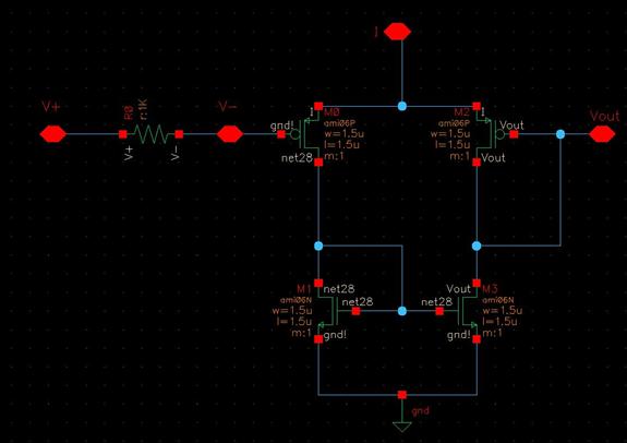
The objective of the project is to design an imager chip for laser-scanned 3-D depth/range finding. The project is divided into two modules: Pixel Array/Centroid Detection and Analog-to-Digital Conversion (ADC). The pixel array/centroid detector tracks the centroid of the...
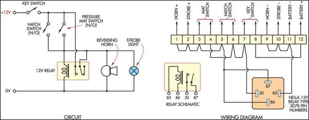
This cost-effective burglar alarm utilizes a 12V strobe light and a truck reversing horn as the visual and audible alarm outputs. The alarm mechanism consists of a 12V horn relay and several pressure mat switches. This straightforward design ensures...

A significant aspect of the soundscape effect appears to stem from adjusting the potentiometers while playing. A request has been made for a version that utilizes slide resistors instead of potentiometers, mounted on foot pedals for real-time manipulation during...