
Q-multiplier filter circuit
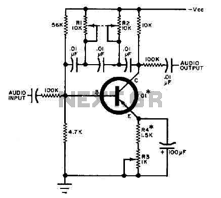
All transistors with a beta greater than 50 are suitable for this application. It is important to select a value for resistor R4 that ensures the circuit does not oscillate when R3 is set for a minimum bandwidth, which corresponds to higher tuning.
The circuit operates by utilizing a transistor amplifier configured in a feedback arrangement, where the tuning capability is achieved through careful selection of passive components. The feedback network, comprised of capacitors and resistors, directly influences the gain and frequency response of the circuit. The arrangement allows for fine-tuning of the audio frequencies, making it ideal for applications requiring precise audio selection.
Transistor Q1 plays a pivotal role in amplifying the input audio signal while maintaining stability in the feedback loop. The choice of resistors R1 and R2 is critical, as they set the initial biasing conditions for Q1, thereby affecting the overall gain and frequency characteristics of the circuit. Grouping R1 and R2 can facilitate easier adjustments and improve the thermal stability of the circuit.
The potentiometer R3 serves as a variable resistor that enables the user to modify the sharpness or selectivity of the circuit's response curve. A higher resistance value in R3 results in a narrower bandwidth, which enhances the circuit's ability to isolate closely spaced audio frequencies. Conversely, reducing the resistance widens the bandwidth, allowing for a broader range of frequencies to be processed.
To ensure optimal performance, the selection of resistor R4 is crucial. It must be chosen to prevent unwanted oscillations that can occur at higher tuning settings. This consideration is essential for maintaining the integrity of the audio signal and ensuring that the circuit functions as intended without introducing distortion or instability.
In summary, this circuit exemplifies a finely tuned audio selection system, leveraging the properties of transistors and passive components to achieve precise frequency adjustments for audio applications. Proper component selection and configuration are vital for achieving the desired performance characteristics.This circuit is selective for the tuning adjustment between two closely spaced tones audio. The frequency is dependent on the selective value capacitors and resistors in the feedback circuit between the collector and base of Q1. With the values shown, the frequency can be "tuned" to a hundred cycles or so-around 650 Hz Ri and R2 should be grouped.
R3 potentiometer transmitter determines the sharpness of the response curve. All transistor having a beta greater than 50 can be used. Select a value for R 4 so that the circuit will not oscillate when R3 is fixed for a minimum bandwidth (higher tuning). 🔗 External reference
Related Circuits
The 8-pin 555 timer is one of the most versatile integrated circuits (ICs) available, utilized in numerous projects. With minimal external components, it can be employed to construct various circuits, many of which do not pertain to timing applications....
Aux Send is an in-studio performance web show and podcast dedicated to showcasing unique, diverse, and talented independent musicians. Aux Send serves as a platform for independent musicians, providing them with an opportunity to perform and share their artistry in...
The circuit was designed to create ten different frequency bands that can be processed by a single graphic equalizer to produce and maintain a predetermined frequency response. The described circuit is a graphic equalizer that utilizes a multi-band approach to...

This design outlines a sensor circuit that utilizes an LED as a light sensor. The operational control and amplification of the output are managed by a 1458 integrated circuit (IC), which functions as an operational amplifier (op-amp). The circuit...
This circuit operates at potentially lethal 220V AC mains voltage. The circuit should be built and used only by individuals who know how to safely work with such dangerous voltages and how to construct the circuit to ensure safety....
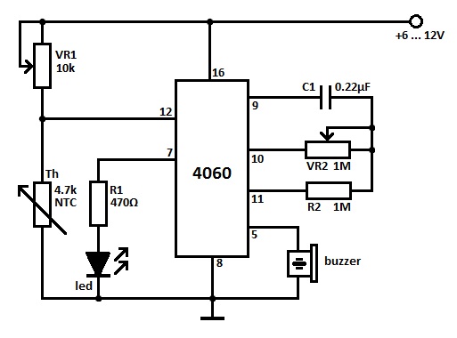
Two heat sensor circuits are presented. The first circuit is constructed using a 4060 integrated circuit (IC), while the second circuit is simpler and contains fewer components. This serves as a conceptual idea. The first heat sensor circuit utilizing the...