
Dynamic Audio Mixer
The dynamic mixer circuit is designed to effectively blend two audio signals, where the primary input (Input A) directly influences the gain of the secondary input (Input B). This is accomplished through a feedback mechanism that utilizes an averaging function implemented in Integrated Circuit 1 (IC1). The choice of IC1 as either an NE571N or NE570N is significant due to their specific functionalities in audio processing, particularly in handling dynamic range compression.
The resistors R1, R2, and R3 are crucial for setting the levels of each input signal. R1 ensures that Input A is properly conditioned before mixing, while R2 adjusts the level of Input B that feeds into the modulator, allowing for precise control over the gain modulation process. R3 is responsible for managing the modulating signal's amplitude, ensuring that the gain adjustment is responsive to variations in Input A.
The average AC signal at pin 2 of IC1 is pivotal, as it dictates the output level at pin 3, effectively controlling the gain of Input B based on the amplitude of Input A. This dynamic relationship allows the mixer to adaptively respond to the audio signals, providing a more integrated sound.
The processed primary signal is transmitted to IC2, an NE5534N low-noise operational amplifier, through capacitor C1 and resistor R7. This operational amplifier is known for its high fidelity and low distortion, making it suitable for audio applications. The gain-modulated signal from IC1 is introduced at pin 5 of IC2, where both signals are summed to create the final output.
To accommodate user adjustments, potentiometers R4 and R6 are incorporated. R4 allows for fine-tuning of the DC offset, ensuring that the mixed output is centered appropriately within the desired voltage range. R6 is used to minimize distortion, enhancing the overall audio quality of the mixed signal.
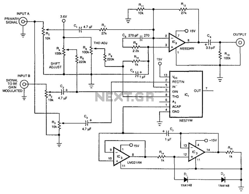
Finally, the filtering section composed of IC3, capacitor C7, resistors R14 and R15, and diodes D1 and D2 is essential for refining the output signal. This filter serves to eliminate unwanted noise and artifacts that may arise during the mixing process, ensuring that the final audio output is clean and professional-grade. The careful selection of components and their arrangement in this dynamic mixer circuit exemplifies a well-thought-out approach to audio signal processing. The dynamic mixer combines two audio inputs by adding the primary signal, Input A, to a gain-controlled signal, Input B . The unusual aspect of this circuit is that the average voltage level of Input A controls the gain of Input B. IC1 has the averaging function and many of the specialized gain blocks that the circuit requires· Rl sets the level of the primary input, Input A, to be passed to the output.
R2 governs Input B"s level to the modulator, while R3 sets the level of the modulating signal. IC1 can be either an NE571N or an NE570N. The average ac signal at pin 2 controls the amount of signal that shows up at ICl"s output, pin 3. The primary signal gets to IC2, an NE5534N low-noise op amp, via CI and R7; the gain-modulated secondary signal arrives via pin 5 of IC1. IC2 sums the two signals. Potentiometers R4 and R6 make dc-offset and distortion adjustments, respectively. IC3, C7, R14, R15, Dl, and D2 form a filter for IC1. 🔗 External reference
Related Circuits
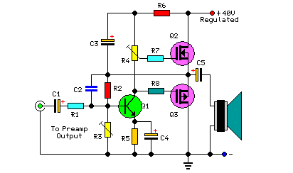
This project includes a preamplifier, tone controls, a regulated DC power supply, and delivers 18 watts into an 8-ohm load and 30 watts into a 4-ohm load. The circuit design comprises several key components that work together to create...
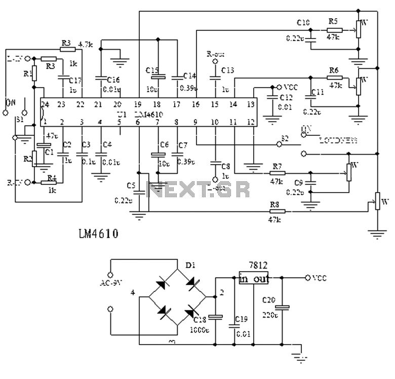
The LM4610 is a product from a US company, succeeding the LM1036, and represents a new class of high-end Hi-Fi tone integrated circuits (ICs). It serves as an ideal alternative to the LM1036, utilizing a two-channel DC voltage to...
This circuit is used to convert a mono audio signal into a stereo signal that can be panned between the left and right channel by a 0-10V control signal, it is intended for analog synthesizer systems. The circuit design focuses...
This circuit uses two quad op-amps to form an eight LED audio level meter. The op-amp used in this particular circuit is the LM324. It is a popular IC and should be available from many parts stores. The 1K...
White noise (the sound you hear when a TV is tuned to a non-existent station) has a frequency characteristic which raises the power level by 3dB with each increasing octave, and is not suitable for response testing (and will...
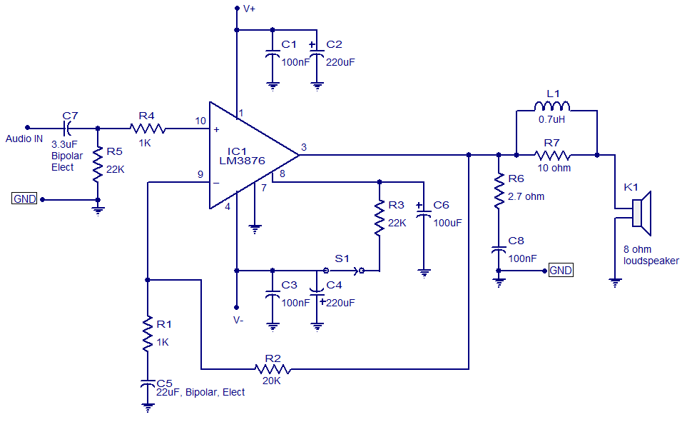
LM3876-based 50-watt audio amplifier circuit. Operates from +/-35V DC. Simple design, low noise. The LM3876 is a high-performance audio power amplifier designed for driving speakers in various audio applications. This particular circuit configuration enables the amplifier to deliver up to...