
8 LED`s Audio VU Meter
This circuit employs two quad operational amplifiers (op-amps) configured to create an eight-segment LED audio level meter. The LM324 IC, which contains four op-amps in a single package, is utilized for this purpose due to its availability and versatility. The circuit operates by detecting audio signal levels and illuminating corresponding LEDs based on the intensity of the input signal.
The design incorporates 1K resistors, which play a critical role in setting the threshold levels for each LED. These resistors ensure that each LED activates at specific audio levels, providing a visual representation of the audio signal's amplitude. It is important to note that while the resistor values can be modified, values exceeding 5K may result in certain LEDs not activating, which could limit the functionality of the meter.
The circuit's architecture allows for easy expansion. Additional op-amps can be integrated to increase the number of LED segments, thus providing a more granular level of audio signal representation. The flexibility of the circuit design permits the use of various op-amps, provided that the pin configurations are correctly referenced and connected.
In addition to the 1K resistors, a 33K resistor is included in the schematic. This component functions to stabilize the circuit and prevent unwanted oscillations, ensuring reliable performance. Careful attention to the layout and connections of the components is essential for optimal operation of the audio level meter. Overall, this circuit serves as an effective tool for visualizing audio levels in various applications, from simple audio projects to more complex sound systems.This circuit uses two quad op-amps to form an eight LED audio level meter. The op-amp used in this particular circuit is the LM324. It is a popular IC and should be available from many parts stores. The 1K resistors in the circuit are essential so that the LED`s turn on at different audio levels. There is no reason why you can`t change these resistors, although anything above 5K may cause some of the LED`s to never switch on. This circuit is easily expandable with more op-amps, and is not limited to use with the LM324. Pretty much any op-amp will work as long as you look up the pinouts and make sure everything is properly connected. The 33K resistor on the schematic is to keep 🔗 External reference
Related Circuits
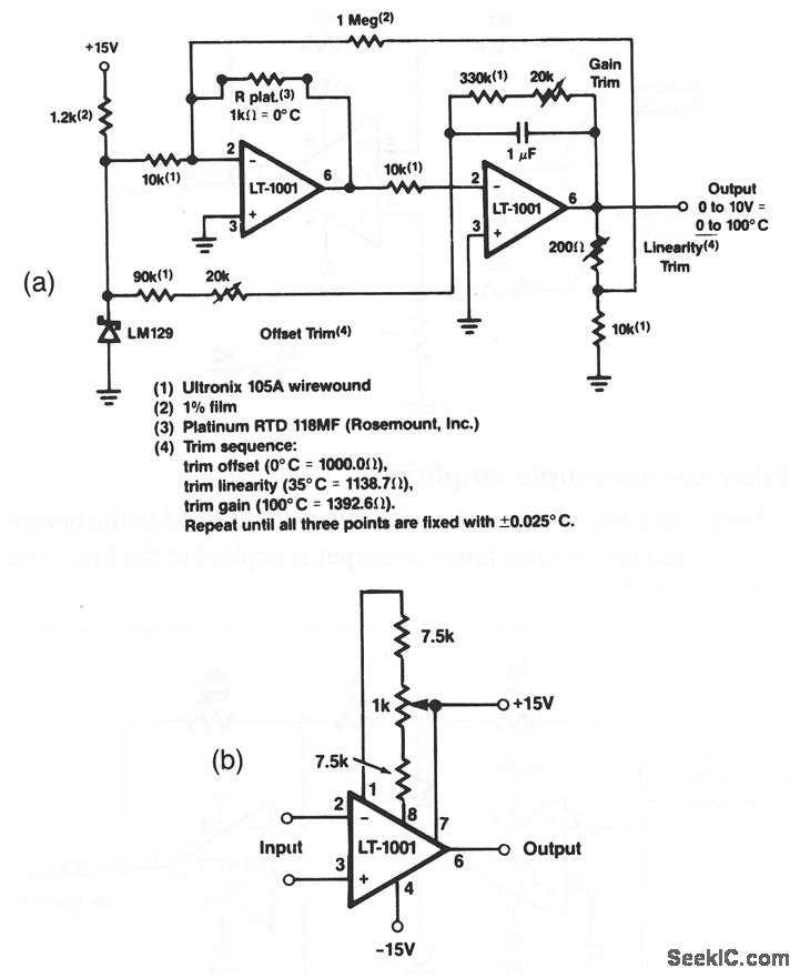
This circuit demonstrates an accuracy of ±0.025 °C across a temperature range of 0 °C to 100 °C, based on the specified values. The LT-1001's input offset voltage and its temperature drift are permanently calibrated to a low level...
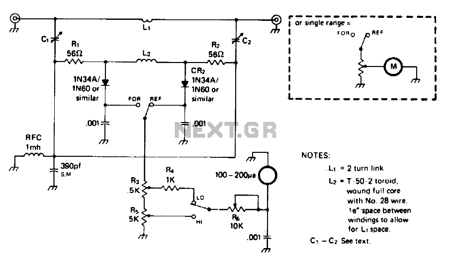
The circuit is not frequency sensitive. Its calibration will be accurate over a wide frequency spectrum, such as the entire amateur HF spectrum, if the values of L2, the voltage divider capacitors C1, C2, and C3, and the resistances...
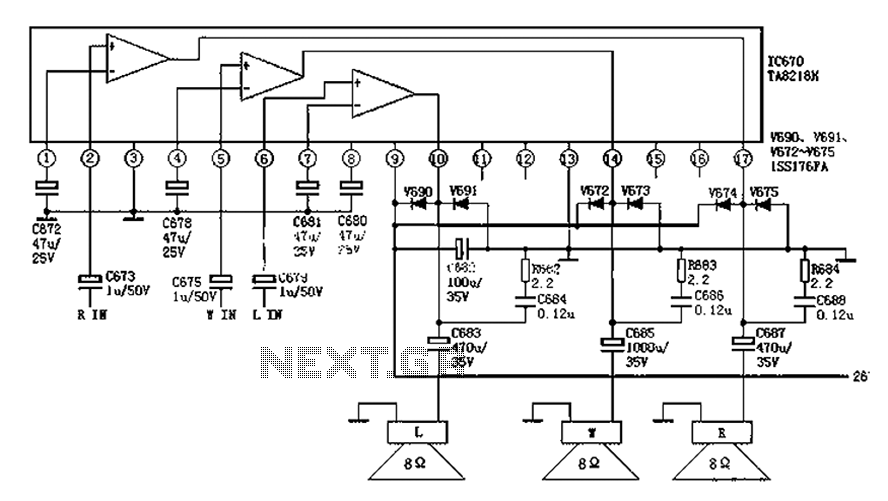
The audio circuit depicted in the figure is commonly utilized in color television systems. The pin functions and reference voltages for the TA8218AH are as follows: Pin 1: 1.9V - inverting input; Pin 2: 2.1V - R-channel audio signal...
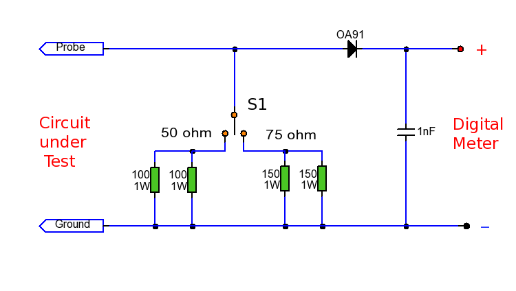
This RF probe is designed for use at High Frequency (HF) or Ultra High Frequency (UHF) with both 50 and 75 ohm coaxial cables. It can measure RF voltage under both load and no-load conditions, enabling it to function...
In this circuit, a simple calculator, in conjunction with a COB (chip-on-board) from an analogue quartz clock, is used to make a telephone call meter. The calculator enables conversion of STD/ISD calls to local call equivalents and always displays...
This document describes a simple 2.4 GHz SWR meter that utilizes surplus microwave hardware. The main component is a MECA -20/-20 dB Directional Coupler, which operates within a frequency range of approximately 700 MHz to 2.5 GHz. This directional...