
Volume Control circuit

The described circuit functions as a digital volume control system, incorporating a range of discrete components to manage audio levels for both left and right channels. The volume control is facilitated by two sets of switches, S2 and S3 for the left channel, and S4 and S5 for the right channel. This dual-channel setup ensures independent volume adjustments, enhancing user experience.
The integration of IC2, a presetable up/down counter, allows for precise volume adjustments. When switch S2 is activated, IC2 counts upwards, and when S3 is pressed, it counts downwards. The BCD output from IC2 is crucial as it drives the address inputs for the analogue multiplexers, IC3 and IC4. IC3 serves as a level indicator, while IC4 operates as a digital potentiometer. The selection of one out of sixteen channels is managed through the analogue switches, which are activated based on the BCD output.
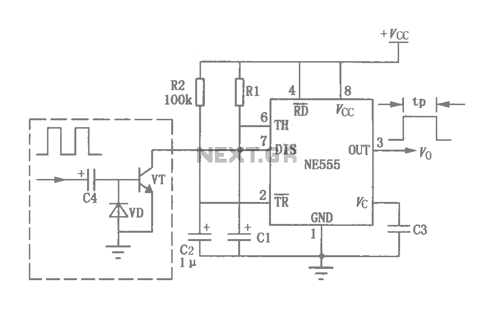
The use of a 555 timer (IC1) configured in astable mode generates a clock signal to facilitate the counting process. The frequency of this clock can be adjusted through the resistors R44, R45, and capacitor C6, enabling customization of the volume adjustment speed. The 1µF capacitor (C4) plays a critical role in filtering out noise that could interfere with the audio signal, ensuring a clean output.
Resistors R6 and R8 are strategically placed to stabilize the quiescent operating voltage, preventing distortion in the audio signal as it passes through the preamplifier stage. Capacitors C2 and C3, along with resistor R7, are employed for effective audio filtering and DC blocking, further enhancing audio quality.
The logarithmic scaling achieved through resistors R9 to R23 provides a more intuitive volume control experience, allowing for finer adjustments at lower volumes while still accommodating higher volume levels. This careful selection of components and their configurations ensures that the circuit operates efficiently and effectively, delivering a high-quality audio experience.Switch S2 is used for increasing and switch S3 is used for decreasing the volume. Similarly, switches S4 and S5 are provided for second channel (right channel) volume control. Also, pin 14 of IC2 can be connected to IC 74193 pin 14 (clear input) of the right channel volume control circuit. The volume control circuit of right channel will be identical to that of the left channel circuit (shown here) except that IC1, IC5 and push-to-on switches are not to be duplicated.
A 1µF electrolytic capacitor (C4) is used to prevent switching noise. Resistors R8 and R6 are used to fix the quiescent operating voltage level at half the supply voltage for avoiding distortion of the audio signal from the preamplifier. Capacitors C2, C3 and resistor R7 are provided for proper filtering of the audio and blocking DC component. An exact logarithmic scale of resistors R9 through R23 produces a pleasing and smooth control. Circuit of a digital volume control using six discrete ICs, including a 5V regulator, is presented. IC1 (555) is configured to function as astable flip-flop. Its frequency or period may be adjusted by proper choice of resistors R44, R45 and capacitor C6 combination.
Here it is for 0.3 second period. IC2 is a presetable up/down counter. In this circuit up-mode is used for increasing and down-mode is used for decreasing the volume. IC3 and IC4 are 16-channel analogue multiplexers which function as analogue switches. Here IC3 is used as level indicator while IC4 is used as a potentiometer. Soon after the power is switched on, switch S1 is to be pressed to reset the whole system. When switch S2 is pressed, IC2 counts up the number of pulses and the result is available in the form of BCD output. IC6 is used as an interface between TTL and CMOS ICs. The BCD output controls the address input lines of IC2 and IC3, and selects/switches one, out of sixteen channels, by turning on the appropriate analogue switch.
In the circuit, IC4 is used as a potentiometer by connecting 15 resistors (R9 through R23) between each of its 16 input pins and a resistor / capacitor combination of C2, C3 and R7 at its output. The values of resistors R9 through R23 can, of course, be selected as desired. Here the resistors have been selected for a logarithmic scale. 🔗 External reference
Related Circuits
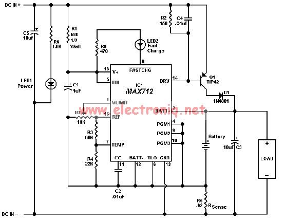
The MAX712 charger requires a power supply with an output voltage that is at least 1.5V higher than the maximum battery voltage. Charge completion is determined by a voltage-slope detecting analog-to-digital converter, a timer, and a temperature window comparator. The...
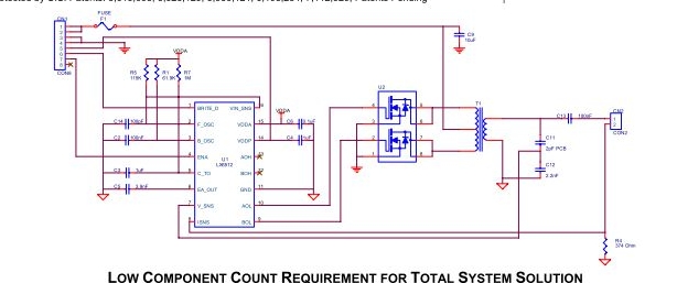
Microsemi's LX6512 is a cost-effective, Direct Drive CCFL (Cold Cathode Fluorescent Lamp) controller. The integrated controller is optimized to drive CCFLs (Cold Cathode Fluorescent Lamps). The Microsemi LX6512 is designed to provide efficient and reliable operation for driving Cold Cathode...
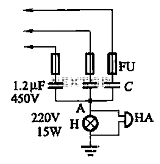
A 3-phase power system poses risks to electrical equipment, particularly asynchronous motors. To detect phase failure, an alarm circuit can be implemented. When the power supply is normal, the voltage at point A is approximately 0V, and no alarm...
The initial program will sweep the servomotor from counterclockwise (CCW) to clockwise (CW) and then back again. The program is designed to illustrate the principles of controlling a servo using the PIC Basic language. The schematic is referenced in...
This circuit was originally a type of power-delay control circuit, where the delay time is determined by the timing elements R1 and C1. Additionally, with the inclusion of a "watchdog" circuit, it can be utilized as a monitoring circuit...
The circuit depicted in FIG. 1 generates a high-voltage signal for controlling the capacitance of barium strontium titanate (BST) capacitors. By applying voltages of V and 3V to the appropriate terminals, the capacitance of the BST can be modified....