
AUTO ALARM

The alarm circuit operates using a combination of analog timing and visual indicators to enhance user convenience and security. The time delay mechanism, governed by the R1/C1 combination, is critical for allowing the motion sensor to stabilize, which is essential in preventing false alarms. The bi-colored LED1 serves as a visual status indicator, transitioning from green to red to inform the user of the system's state. The use of a 555 timer integrated circuit (U2) provides reliable timing functions, while the 3905 timer (U1) ensures that the alarm remains inactive during the delay period.
The relay K1 is a pivotal component in the circuit, acting as a switch that activates the siren when the system is armed. The duration of the alarm sound is adjustable through the selection of R4 and C2, allowing for customization based on user preference or application needs. The manual reset capability enhances user control over the system, ensuring that the alarm can be easily rearmed after an event.
The design incorporates safety features, including the use of diode D1, which prevents back-feeding of current that could inadvertently activate the LED during the alarm state. The proper connection of resistors R4 and R5 to the +V bus is essential for maintaining circuit stability and preventing false triggers, which could compromise the reliability of the alarm system.
Overall, this alarm circuit exemplifies a well-engineered solution for vehicle security, combining user-friendly features with robust functionality to protect against unauthorized access while accommodating the user's day-to-day activities.In operation, the alarm circuit allows a 0-47 second time delay, as determined by the R1/C1 combination, after the switch is armed to allow the vehicle`s motion sensor to settle down. This allows you time to get a bag of groceries out of the trunk and not have the hassle of juggling the groceries and the key switch at once.
During the time delay, half of LED1, which is actually a single, bi-colored, three-legged common cathode device, lights green. At the same time, pins 8 and 4 of U2 (a 555 oscillator/timer) are held low by U1 (a 3905 oscillator/timer), causing the alarm to remain silent.
Once the delay is over, LED1 turns red, indicating that the circuit is armed. At that point, a ground at pin 2 of U2 forces pin 3 of U2 high, closing the contacts of K1 and sounding the siren for a time duration determined by R4 and C2. Once the time has elapsed, pin 3 is pulled low, K1 opens, and the circuit is again ready to go. The circuit can be manually reset by the simple expedient of opening and closing the key switch. Potentiometer R3 controls the LED`s illumination intensity. Diode Dl ensures that the green segment of LED1 is fully extinguished when Q1 is turned on-which turns the LED to red.
Resistors R4 and R5 must be connected to the +V bus, not to pin 7 of U1, otherwise U2 will mysteriously trigger itself each time the initial delay ends. 🔗 External reference
Related Circuits
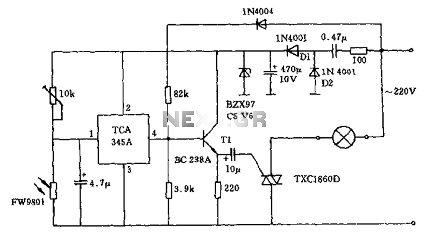
A 200W lamp switch control operates at a power supply voltage of 220V. It automatically turns the light on or off based on ambient illumination levels, specifically activating at approximately 100 lux. In low light conditions, a time-sensitive resistor...

This page outlines the modifications made to a SkyWatcher dual-axis EQ5/EQ4 motor controller to enable autoguiding via the parallel port from a PC. The modification allows the RA+, RA-, Dec+, and Dec- buttons to be activated from the PC...
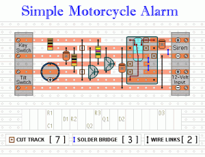
The following circuit is a simple, inexpensive, and easy-to-build motorcycle alarm. The circuit requires only two transistors to drive a relay, which acts as a switch to activate a buzzer. Any number of normally-open switches can be used. Mercury...

This alarm features both open-loop and closed-loop detection systems along with an automatic alarm shutoff mechanism. It provides a 15-second delay for exit and entrance. Additionally, the alarm activation time can be adjusted from 1 to 15 minutes. The alarm...
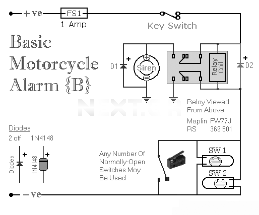
Two simple relay-based motorcycle alarm circuits. These are easy to build and can be used to protect motorcycles, but they also have many other applications. If relays with 6-volt coils are used... The motorcycle alarm circuits described consist of two...
When the resistance value of temperature, light, pressure, or any other resistive sensors (Rs) drops below a certain threshold, which can be adjusted by a preset. In electronic circuits, resistive sensors such as thermistors, photoresistors, and piezoresistors are commonly used...