
General Purpose Alarm Circuit for Resistive Sensor

In electronic circuits, resistive sensors such as thermistors, photoresistors, and piezoresistors are commonly used to monitor environmental conditions. These sensors change their resistance in response to variations in temperature, light intensity, and pressure, respectively. The output from these sensors can be utilized in various applications, including environmental monitoring systems, automatic lighting controls, and pressure detection systems.
When the resistance of a sensor, denoted as Rs, falls below a predetermined threshold, it can trigger specific actions in the circuit. This threshold is typically set using a variable resistor (potentiometer) that allows for fine-tuning according to the specific application requirements.
For example, in a temperature monitoring system using a thermistor, if the temperature rises and causes Rs to drop below the preset threshold, the circuit can activate a cooling system or send an alert signal. Similarly, in a light-sensitive application, if the ambient light decreases and Rs falls below the set point, the circuit can turn on an LED or activate a relay to control other devices.
The circuit design may include an operational amplifier configured as a comparator to monitor the voltage drop across Rs. When the voltage corresponding to Rs falls below the reference voltage set by the potentiometer, the comparator output will switch states, triggering subsequent actions in the circuit. This setup allows for precise control and responsiveness to environmental changes, enhancing the functionality and automation of electronic systems.When the resistance value of a temperature, light, pressure,? or any other resistive sensors? Rs drops below a certain point? (adjusted by a preset. 🔗 External reference
Related Circuits
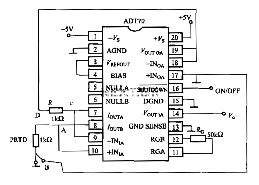
The AD170 basic electrical parameters include a temperature coefficient of 25 ppm/°C and a temperature measurement accuracy of ±1°C, with a maximum temperature range of -200°C to +100°C. The power supply required is +5V or -5V, and the operating...

RF Wireless Data Transfer communication circuit diagram. A wireless communication interface was implemented to facilitate data transfer from one point to another using RF technology. The RF Wireless Data Transfer communication circuit utilizes radio frequency (RF) technology to establish a...

The primary objective is to present the circuit diagram and describe the software utilized. A UDP application is employed to transmit commands to the microcontroller, which subsequently activates or deactivates the relay. It is anticipated that TCP implementation could...

The circuit provides an 8-ohm output for connecting communication receivers and low-impedance speakers or headphones, featuring harmful interference suppression for continuous random voice transmission. The passband ranges from 55 to 2530 Hz with a 3 dB bandwidth. Inductors L1...

The first circuit was designed for the situation where a hijacker forces the driver from the vehicle. If a door is opened while the ignition is switched on - the circuit will trip. After a few minutes delay -...

The circuit utilizes a transistor (VT) and a voltage regulator (VSL) to create a constant current source, employing three regulators to enhance the performance of the regulator circuit. The described circuit employs a transistor (VT) in conjunction with a voltage...