
Auto Fuse for power supply

The described power supply circuit is designed to provide stable output voltage while ensuring protection against overcurrent conditions. It operates with a maximum output voltage of 45V DC, making it suitable for laboratory applications where precise voltage regulation is essential. The core of the circuit involves three transistors: Q1 and Q2 for current regulation, and Q3 for overcurrent protection.
Transistor Q2 is the primary regulating element, which enters saturation under normal operating conditions, allowing current to flow through R1, which acts as a base resistor for Q1. This configuration ensures that Q1 remains in an 'on' state, enabling the circuit to maintain the desired output voltage. The output voltage is designed to be approximately 2V less than the input voltage, ensuring that the circuit operates efficiently.
In the event of a short circuit, the voltage drop across R2 increases to 0.7V, triggering Q3 to conduct. This action reduces the voltage across the collector-emitter junction of Q3 to 0.3V, effectively limiting the output voltage and protecting the circuit from excessive current flow. The interaction between Q1 and Q2 is crucial, as Q1 will only activate when the voltage between its base and the emitter of Q2 exceeds 1.4V. Under overcurrent conditions, the combined voltage drop across R2 and Q3 ensures that the system remains within safe operating limits.
The circuit also features a table specifying the values of resistors R1 and R2 and the transistor types Q1, Q2, and Q3, tailored to different maximum current intensities (Imax). This design allows for flexibility in component selection, as long as the replacements match the electrical characteristics necessary for the circuit's operation. Overall, this power supply circuit is a robust solution for laboratory environments, providing both voltage stabilization and overcurrent protection.The power supply, with electronic stabilisation - mainly those of laboratories - it should they are protected from ??over current?? that emanates from short-circuits, erroneous association or damage of repaired appliance. The circuit offers effective protection in power supply with output voltage through to 45V DC. Transistor Q3 of is type in all cases BC148, while the types of Q1-2, as well as R1-2, depend from the biggest intensity of current, according to the table.
The entry is connected in the exit power supply. Under regular conditions of work, the Q2 turn on, completely via the R1-Q1 and functions in the saturation. The output voltage is 2V roughly lower than the voltage of supply. If grow the dip of voltage, in the R2 at 0.7V. because short-circuit, then conduct the Q3 and the voltage between the collector and his emitter is 0.3V. the Q1-2, however is driver only when his voltage between the base of Q1 and emitter of Q2 is 1.4V at least.
But in case of overcharge, this voltage is 0.7V+0.3V=1V, with result the circuit is regulated automatically in the predetermined biggest intensity. The transistors that I give in the table can be replaced with corresponding, it is enough they suit their characteristics.
Imax (A) R1 (?) R2 (?) Q1 Q2 Q3 5 100 0.12 2?1613 2N3055 BC148 0.5 1000 1 BC107 2N1613 BC148 0.1 4700 4.7 BC107 2N1613 BC148 🔗 External reference
Related Circuits
Features: 3-12 V, 1 A, over-current protection. This is a simple yet reliable device based on one of the oldest integrated voltage regulators, the LM723. R2 sets the output voltage. The maximum current is determined by the value of...
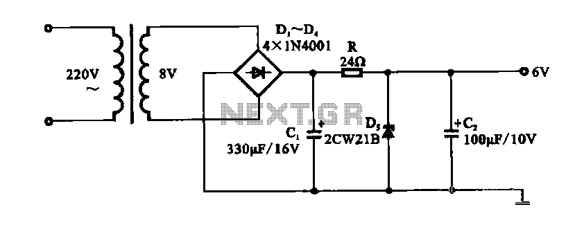
A DC shunt regulator power supply circuit is presented, which operates in parallel with a radio circuit. The circuit begins with an AC voltage of 22V, which is stepped down to 8V using a transformer. The 8V AC voltage...
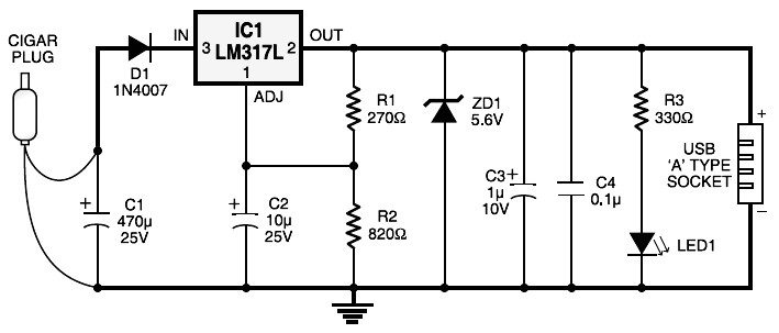
Cigar lighter plug to USB power socket. This circuit converts a 12V DC source from a car cigar lighter plug into a USB power socket with a 5V DC output. This circuit can be used to power 5V electronic...
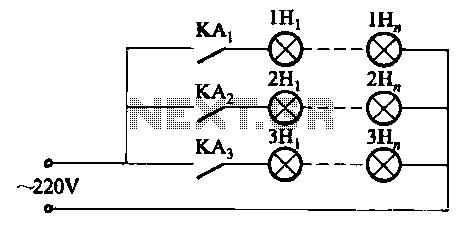
The relay control system utilizes multiple pairs of contacts, allowing for the connection of higher power lamps in parallel. The circuit design is straightforward; by altering the capacitance of the capacitor, different flashing frequencies can be achieved. The described circuit...
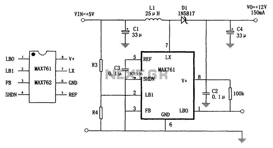
The circuit depicted in the figure illustrates an efficient, low-power step-up DC-DC converter, the MAX761, along with a few external components, which functions as a +5V to +12V boost power supply. Its characteristics include a conversion efficiency of 86%...
Power an RS232-TTL converter circuit using the serial port to eliminate the need for an external power supply. It has been noted that the DTR, RTS, and TD pins can facilitate this. Since the TD pin is already utilized...