Auto lights-on reminder
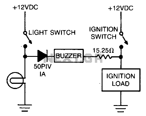
The alarm consists of a diode, buzzer, and a limiting resistor. The diode functions as a switch that enables the buzzer to activate only when the light switch is closed and the ignition is turned off.
The circuit described utilizes a diode, a buzzer, and a limiting resistor to create an alarm system that operates under specific conditions. The diode is critical in ensuring that the buzzer is activated only when the light switch is in the closed position and the ignition is off. This configuration prevents the buzzer from sounding unintentionally, thereby enhancing the reliability of the alarm system.
In this schematic, the diode is connected in series with the buzzer and the limiting resistor. The limiting resistor is required to control the current flowing through the buzzer, ensuring that the buzzer operates within its specified current rating, thus preventing damage. The diode is oriented such that it allows current to flow in one direction only, effectively acting as a gate that closes when the light switch is open or when the ignition is on.
When the light switch is closed and the ignition is off, the circuit is completed, allowing current to flow through the diode and energize the buzzer. This results in the buzzer sounding an alarm, alerting the user to the condition. Conversely, if either the light switch is open or the ignition is turned on, the diode blocks the current, and the buzzer remains silent.
This alarm system can be effectively utilized in various applications, including automotive environments, where it is crucial to monitor the status of the light switch and ignition for safety and operational efficiency. Proper selection of the diode, buzzer, and resistor values is essential to ensure optimal performance and reliability of the circuit.The alarm is composed of a diode, buzzer, and limiting resistor The diode serves as a switch which allows the buzzer to sound off only when the light switch is closed and the ignition is turned off.
