
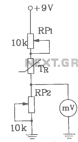
Interface Circuit for PC Soundcard Oscilloscope

This interface circuitry serves as a valuable tool for hobbyists and engineers seeking to analyze electrical signals without the need for expensive dedicated oscilloscopes. The design accommodates two input channels, each capable of handling signals up to 1.2 V, which is crucial for protecting the sound card's input from potential damage due to over-voltage conditions. The schematic layout includes clear demarcations for the input channels and a common ground reference, ensuring proper signal integrity during measurements.
The integration of protection diodes is an essential feature, as it safeguards the sound card from voltage spikes that could occur during operation. The 3.5 mm stereo jack connections facilitate easy interfacing with the sound card, allowing for straightforward signal acquisition. The adjustable trimmers enable calibration of the oscilloscope's display to match known voltage levels, enhancing the accuracy of qualitative assessments.
It is important to note that due to the AC-coupling nature of most line-in inputs, the use of pure DC signals is not recommended for calibration purposes. Instead, employing a rectified 5V signal provides an effective means of adjusting the display amplitude. The availability of software tools such as AudioAnalyzer and MultiSine further enhances the functionality of this setup, enabling users to visualize and analyze waveforms on their computers effectively. This combination of hardware and software creates a versatile platform for signal analysis in various applications, making it a practical solution for those working with basic electronic circuits.For simple electronic circuits, it may be sufficient to get a qualitative insight on dedicated electrical signals. This interface circuitry allows to use the line-in input of a standard PC soundcard to be used as a 2-channel oscilloscope.
This setup does not allow for exact measurements, however for some applications, a qualitative insight on dedi cated timing or signal characteristics may be obtained. The interface limits the signals from input channel 1 and 2 to a maximum amplitude of 1. 2 V (over-voltage protection circuitry). At the left side of the schematic below, the two input channels for signal measurement and the common ground are shown. At the right side, next to the protection diodes, the connections for the 3. 5 mm stereo jack to the soundcard (line-in) are drawn. The height of the signal amplitude shown within the OSZI can be adjusted with the two trimmers with signal of known amplitude (e.
g. a rectified 5V signal). Since most line-in are AC-coupled, pure DC signals are not suitable for calibration of the voltage levels. Note: There exist now very nice software tools for your PC soundcard (Windows XP) from Sebastian Dunst: AudioAnalyzer & MultiSine.
See the software section. 🔗 External reference
Related Circuits
T-121 temperature sensor electronic thermometer circuit diagram shown below The T-121 temperature sensor circuit is designed to measure and display temperature readings accurately. The circuit typically consists of a temperature sensor, such as the T-121, which converts temperature variations into...
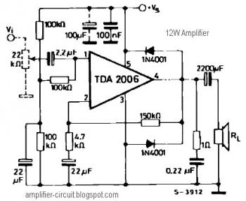
The power amplifier IC TDA2006 provides high output current and has very low harmonic and cross-over distortion. Furthermore, the device incorporates an original (and patented) short circuit protection system that automatically limits the dissipated power to keep the working...
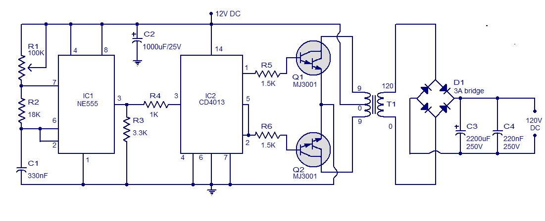
This is a simple circuit designed to convert 12V DC to 120V DC. The circuit comprises two main phases: the inverter stage and the rectifier and filter stage. The NE555 integrated circuit (IC1) is configured as an astable multivibrator,...
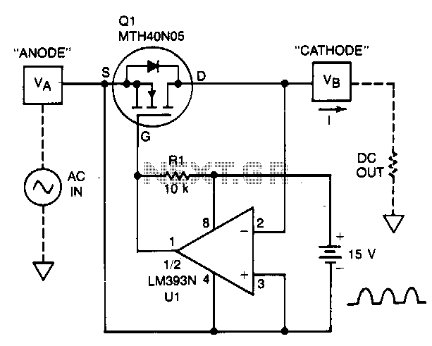
A TMOS power FET, Q1, and an LM393 comparator provide a high-efficiency rectifier circuit. When voltage V1 exceeds V2, the output of U1 becomes high, and Q1 conducts. Conversely, when V2 exceeds V1, the comparator output becomes low, and...
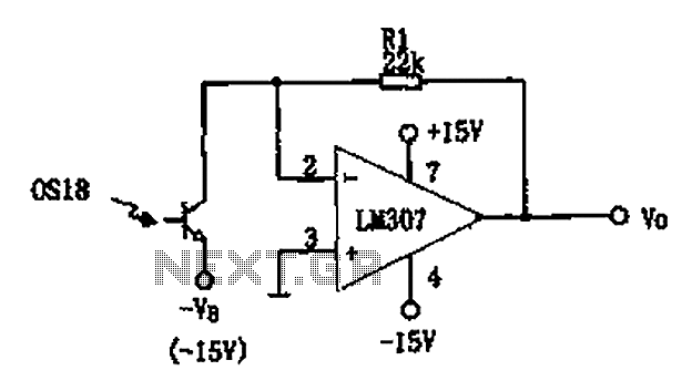
The circuit described is a photoelectric receiver amplifier designed to amplify the electrical signals generated by photodiodes or phototransistors in optoelectronic devices. When the intensity of incident light varies, the photosensitive device generates a corresponding voltage or current. The...
The circuit can be easily built to a small plastic box with telephone connectors in both ends. The circuit takes about 10-20 mA current, so if the circuit is not in use all the time it is best to...