
Automated instrumentation wiring using interference filters

Automated instrumentation wiring employing interference filters is essential for minimizing the effects of electromagnetic interference (EMI) on inverter systems. Inverters, which convert direct current (DC) to alternating current (AC), can generate significant electromagnetic emissions, especially when operating under high load conditions. These emissions can distort the readings of sensitive instrumentation and lead to inaccuracies in measurements.
To mitigate these issues, proper installation practices must be followed. It is recommended that the distance from the meter to the inverter should not exceed 200mm, and the meter should not be positioned on the same layer as the shielding box. This configuration helps reduce the coupling of electromagnetic fields into the measurement circuit, thereby minimizing potential errors.
Grounding is another critical aspect of the installation. The instrument ground terminal must be securely connected to ensure a stable reference point for the measurements and to prevent ground loops, which can introduce additional noise into the system.
The filtering process for the instrument's input cable and power cord is vital for suppressing high-frequency noise. The selected capacitor (0.1μF, 250V) serves to block high-frequency noise while allowing the desired signals to pass through. The inductance of 10mH, with a DC resistance of less than 5Ω, aids in further filtering out unwanted electromagnetic interference. The resistor (100Ω, 1/2W) is included in the design to provide a damping effect, which can help stabilize the circuit and improve the overall response time of the instrumentation.
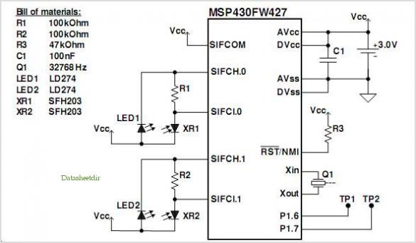
In summary, careful consideration of the installation parameters, grounding practices, and component selection is essential for ensuring accurate and reliable operation of automated instrumentation in the presence of high amplitude electromagnetic waves. Proper implementation of these measures will enhance the performance of the system and reduce measurement errors significantly. Automated instrumentation wiring using interference filters for the inverter is not as harmonic processing and the like, when the work will be radiated field strength of strong , high amplitude electromagnetic wave, if the meter is installed in the automation from its lack of 200mm, placed in not the same layer as the shielding box, the meter may yield additional error birth. This time should be the instrument ground terminal properly connected, then the instrument input cable and power cord for the filtering process, as shown in FIG.
Now the capacitor C selection 0. lFtF, 250V; inductance L take lOmH, DC resistance of less than 5Q; resistor R to select 100n, 1/2W.
Related Circuits
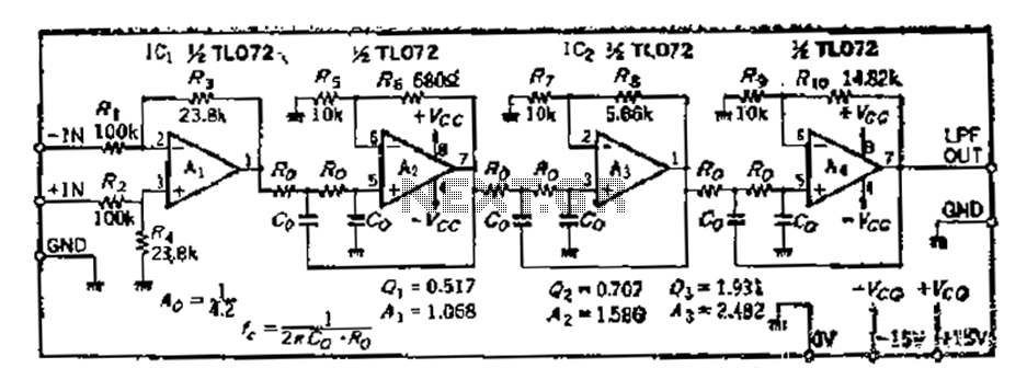
A 36 dB/octave Butterworth filter consists of three sub-structures, each stage containing two filter sections. The design aims to achieve specific 3 dB frequency characteristics. The filter needs to be normalized to a value of 0 across all levels,...
The LH0024 is a small signal integrated circuit (IC) designed for general-purpose switching and amplification due to its low voltage characteristics. Additionally, it utilizes three 1N4148 silicon small signal diodes, which are planar epitaxial devices used for fast switching...
A frequency meter is commonly used in speed sensors, tachometers, and for measuring recurring signals. This frequency-to-voltage converter (FVC) can be utilized to convert frequency into a digital or analog tachometer output. The circuit comprises three main blocks. The...
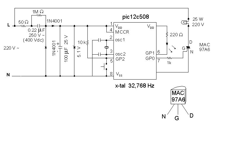
Introduction It is time for the 8-pin microcontroller Microchip PIC12C508, the SAVER V3.2, a new design of a device that controls a night light by turning it on and off. The SAVER V3.2 utilizes the Microchip PIC12C508 microcontroller, which features...
The SP1481E, SP1485E, SP1490E, and SP1491E series transceivers, combined with the SP6652 high-efficiency, high-frequency current mode PWM buck regulator, facilitate the creation of an isolated RS-485 interface capable of providing up to 2kVrms isolation. This configuration supports CAN communication...
The circuit demonstrates the application of the ZN414 integrated circuit (IC) to create a compact AM radio receiver. The ZN414 IC is a combination of a transistor and a tuned radio frequency (TRF) circuit. The ZN414 IC is specifically designed...