
Automatic Ac Line Voltage Selector

The application note focuses on the integration of a PSoC device for the control of a BLDC motor, which is particularly suited for automotive wiper systems due to its efficiency and reliability. The use of LIN Bus 2.0 allows for a seamless communication interface between the motor controller and other automotive systems, ensuring that wiper operations can be effectively managed in response to various conditions.
The PSoC architecture provides flexibility in programming and configuring various peripherals, which is essential for tailoring the motor control algorithms to specific automotive requirements. The implementation details include the configuration of the PWM (Pulse Width Modulation) signals necessary for driving the BLDC motor, along with feedback mechanisms to monitor motor performance and adjust control signals accordingly.
Moreover, the application note elaborates on the LIN Bus 2.0 protocol, detailing how it facilitates robust communication between the motor controller and the vehicle's central control unit. This ensures that the wiper system can respond to inputs such as rain sensors or driver commands, enhancing overall functionality and safety.
The associated part families, CY8C27443 and CY8C29466, are highlighted for their suitability for this application, offering integrated features that streamline the design process. These components come with built-in support for the required communication protocols and motor control functionalities, making them ideal for automotive applications where reliability and performance are paramount.
Overall, this application note serves as a valuable resource for engineers looking to implement a BLDC wiper motor control system using PSoC technology, providing the necessary information to replicate and customize the design effectively.Abstract This Application Note describes PSoC device implementation of a BLDC (Brushless DC) windscreen wiper Motor Controller for automotive applications. LIN Bus 2. 0 is implemented to provide an Interface for controlling wiper operation. This Application Note sufficiently describes the technical details so that the user is familiar with the impo
rtant aspects of the design and is able to recreate the design specific to their exact requirements. This note also describes LIN Bus 2. 0 implementation in detail. Associated Part Family: CY8C27443 and CY8C29466 🔗 External reference
Related Circuits
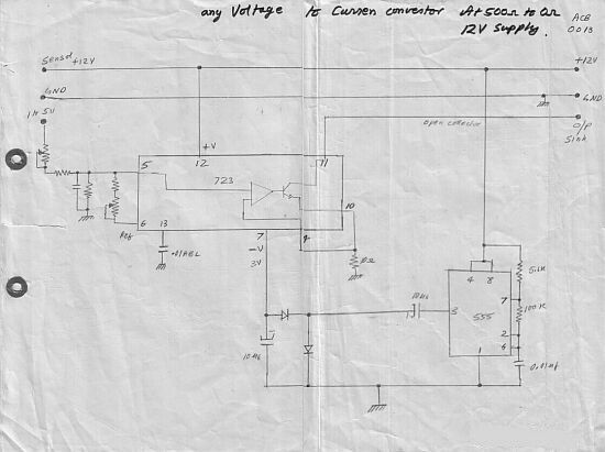
This circuit converts a voltage control output from a process controller into a current control signal, which is necessary when an AC drive or valve requires a current control signal. It operates as a three-wire voltage-to-current loop converter. A...
The clock frequency ranges from 5 kHz to 50 kHz, with a delay time adjustable between 51.2 ms and 5.12 ms. The clock frequency must be at least double the highest audio frequency. The described circuit operates within a clock...
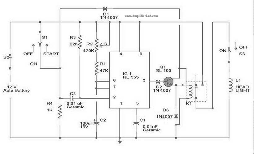
The circuit diagram for the automatic headlights turn-off circuit is presented here. This circuit can be installed in a car. The automatic headlights turn-off circuit is designed to enhance vehicle safety and convenience by ensuring that the headlights are automatically...
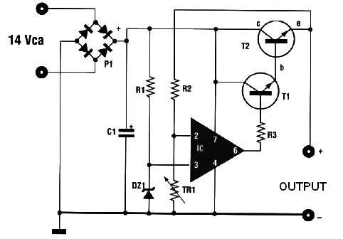
This automatic battery charger circuit is ideal for charging batteries used in alarm systems that require battery buffering. Caution must be exercised when connecting the battery to ensure correct AC polarity. It is essential to meticulously follow the schematic...
This voltage-to-current converter utilizes three operational amplifiers to control a pair of power transistors. The output current is determined by the formula: IOUT = Vin/R6. The output resistance exceeds 50 MΩ, and the output current can vary from 1...
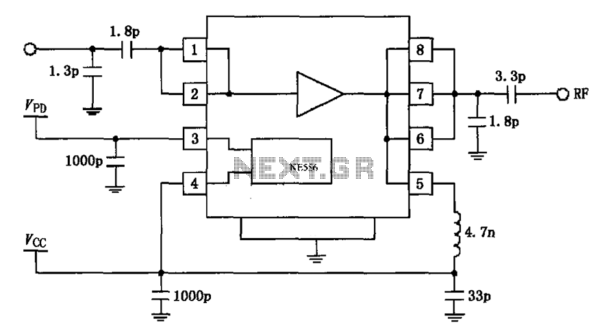
The circuit depicted in the figure is based on the RF2126, a 2450 MHz end-stage linear power amplifier. The radio frequency (RF) signal enters through input pin 1 and is subsequently amplified by the amplifier stages (pins 5, 6,...