
Automatic Car Head Lights Turn-off Circuit

The automatic headlights turn-off circuit is designed to enhance vehicle safety and convenience by ensuring that the headlights are automatically turned off after a predetermined time when the vehicle is parked. This circuit typically utilizes a timer integrated circuit, such as the NE555, which is configured in monostable mode to achieve the desired time delay.
In this circuit, the headlights are connected through a relay, which is controlled by the output of the timer. When the vehicle's ignition is turned off, the timer is activated, initiating the timing sequence. The duration for which the headlights remain on can be adjusted by changing the resistor and capacitor values connected to the timer IC.
The circuit also includes a switch that can be manually overridden to turn off the headlights immediately, regardless of the timer. Additionally, a diode is included to prevent back EMF from the relay coil, protecting the timer IC from potential damage.
For installation, the circuit requires a power source that is only active when the ignition is off, typically sourced from the vehicle's battery. Proper connections to the vehicle's lighting system and the relay are crucial for reliable operation. This automatic headlight turn-off circuit not only prevents battery drainage but also ensures that the vehicle's lights are managed efficiently, contributing to overall vehicle functionality and user experience.The circuit diagram of Automatic head lights turn off circuit has been explained here. This circuit can be installed in a car. 🔗 External reference
Related Circuits
This is a highly sensitive envelope detector designed for AM radio applications. The circuit, illustrated in Figure 1, enables linear detection of weak signals with a modulation depth of 80-85%. The first stage (VT1) functions as a common-emitter amplifier...
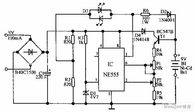
An automatic Ni-Cd battery charger circuit is depicted in the provided image. The internal comparator of the NE555 timer is configured to a reference voltage of 4.7V using a Zener diode. When the voltage at pin 6 exceeds this...
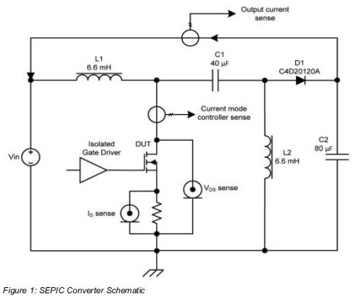
Comparing the performance of 1200V silicon carbide (SiC) MOSFETs with 1200V silicon MOSFETs and IGBTs at high frequency is essential to identify the differences in device losses and power-handling capabilities among these technologies. A demonstration platform has been developed...
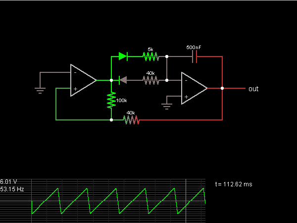
A step sequence can be applied that triggers every other step, allowing the activated steps to rise with each activation. This Low-Frequency Oscillator (LFO) can then be used to modulate other parameters of the plugin to enhance the sound....
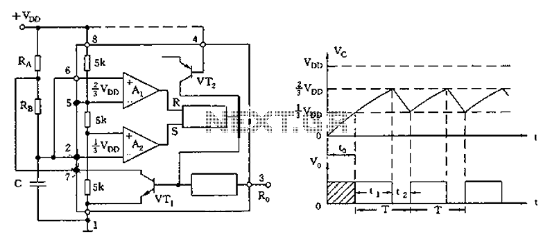
The circuit diagram illustrates the 555 timer (or 556 timer in half configuration) configured in astable multivibrator mode. It features three resistive and capacitive elements connected as shown. In one-shot mode, the trigger terminal (pin 2) is connected to...
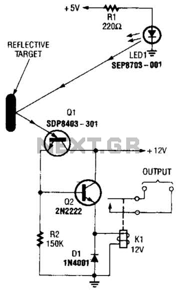
A reflector isolator detects the presence of an object by bouncing light off of it. This technique is useful in circuits that detect when an object is close enough to the sensor. A reflector isolator is a type of optical...