
Automatic AC voltage regulator circuit TXD1742 continuous adjustment

The TXD1742 is an automatic AC voltage regulator circuit designed to provide continuous voltage adjustment, ensuring stable output voltage in varying load conditions. This circuit is particularly useful in applications where voltage fluctuations can adversely affect the performance of electrical devices.
The core of the TXD1742 circuit typically includes a transformer, a rectifier, a voltage regulator IC, and various passive components such as resistors and capacitors. The transformer steps down the high AC voltage to a lower AC voltage suitable for regulation. The rectifier converts the AC voltage to pulsating DC, which is then smoothed by a filter capacitor to provide a stable DC voltage.
The voltage regulator IC is the heart of the circuit, responsible for maintaining a constant output voltage. It continuously monitors the output voltage and adjusts the duty cycle of the control signal to the power switch, which could be a transistor or a thyristor, to regulate the output voltage. The continuous adjustment feature allows for fine-tuning of the output voltage, accommodating different load requirements and ensuring optimal performance.
Additional components, such as zener diodes and operational amplifiers, may be included in the circuit design to enhance voltage regulation accuracy and improve transient response. Feedback loops are often employed to compare the output voltage with a reference voltage, allowing for real-time adjustments to maintain the desired output level.
Overall, the TXD1742 automatic AC voltage regulator circuit is an effective solution for applications requiring reliable voltage regulation, protecting sensitive electronic equipment from the adverse effects of voltage variations. Automatic AC voltage regulator circuit TXD1742 continuous adjustment
Related Circuits
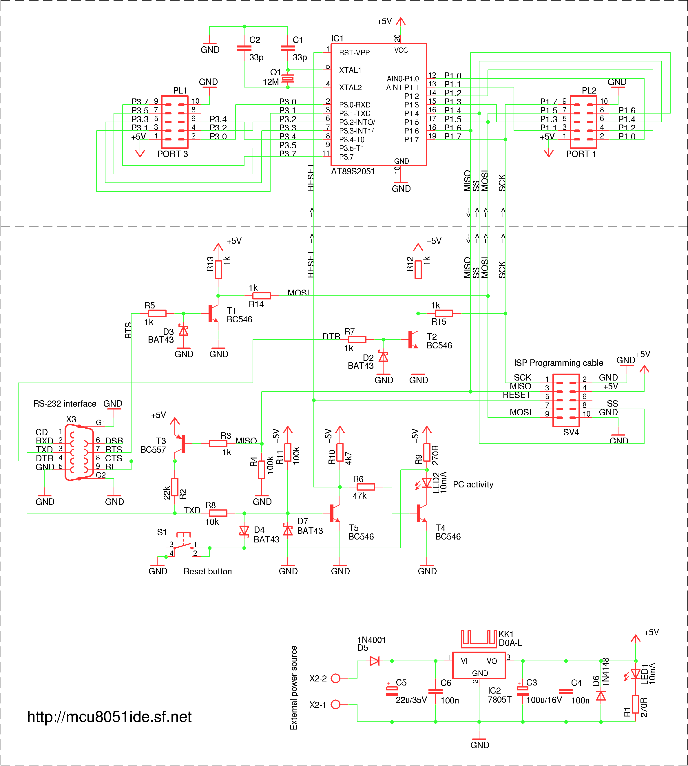
A simple RS-232 ISP programmer designed for AT89Sx devices, intended for educational purposes and hobbyist use. It has been tested with the AT89S2051 and AT89S8253 microcontrollers, utilizing a USB to serial port converter cable equipped with a PL2303 chip....
Designed for communications use, this equalizer circuit utilizes a Mitsubishi M5226P audio equalizer IC to modify frequency response. It operates with a supply voltage ranging from 9 to 20 V. Capacitors C6 through C16 are polyester film capacitors with...
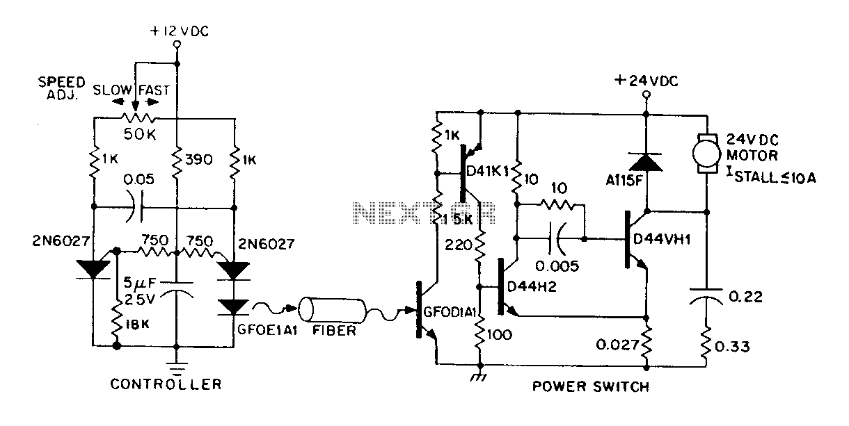
A DC power supply can be controlled through an optical fiber. The circuit includes a small DC motor (1/12 hp) that offers an isolated speed control channel. The control logic operates as an independent module, consuming 300 mW of...
Observing my Boss pedals and how they were switched on and off I figured there must be more to it. It took me only about 4 hours to design and test this circuit. It works very well and I’m...
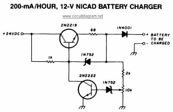
A 12V NiCAD battery charger circuit with a charging rate of 200mA per hour. This circuit initially charges the battery at 75mA until it reaches a full charge, after which the current is reduced to a trickle rate. The...
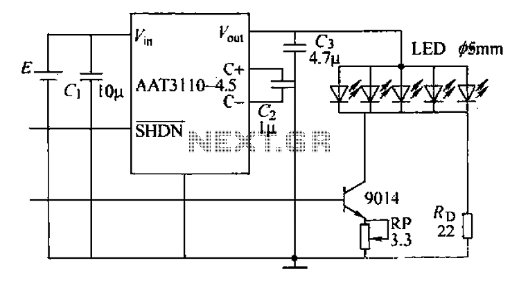
A circuit designed for a phone photo camera flash that delivers a peak current of 200mA. It utilizes the AAT3110-4.5 capacitive charge pump chip to boost and regulate the lithium battery voltage to 4.5V. This voltage powers a series...