
Automatic Battery Charger 6V-12V with Relay cut off by LM324

The automatic battery charger circuit employs the LM324 operational amplifier, which serves as the core component for voltage regulation and monitoring. The circuit is configured to support different battery voltages, specifically 6V and 12V, making it versatile for various applications. The use of switch S1 allows the user to select the appropriate voltage setting for the battery being charged, ensuring optimal charging conditions.
When the battery is connected, the LM324 monitors the voltage level. As the battery charges, the voltage increases until it reaches a predetermined threshold, indicating a full charge. At this point, the LM324 triggers relay RY1, which disconnects the charging circuit from the battery, thereby preventing overcharging and extending the battery's lifespan.
Resistors R1 and R7 play a critical role in determining the charging rate. By adjusting these resistors, the charging speed can be fine-tuned according to the specific requirements of the battery type and capacity. This feature is particularly useful for applications where different battery chemistries may require distinct charging profiles.
The circuit design is straightforward, making it accessible for testing and implementation. When a fully charged battery is connected, R1 and R7 facilitate the operation of relay RY1, confirming that the circuit is functioning correctly. The accompanying circuit diagram provides visual guidance for assembly and troubleshooting, ensuring that users can effectively utilize the charger for their battery maintenance needs.
Overall, this automatic battery charger circuit represents a practical solution for efficiently charging multiple battery types while safeguarding against overcharging, thus promoting battery longevity and reliability.This be battery charger the automatic circuit again interesting circuit. Because of use IC LM324 then make economize. And can charger get both of battery 12V sizes and 6V with the filtration that at S1. Certainly circuit this still base property be when battery have voltage full already, circuit as a result order give Relay RY1 cut the system depa rts battery immediately. For R1 and R7 use for fine decorate the rapidity of the circuit. The test is as a result easy. Lead the battery that have Full voltage wasp with the circuit fines to decorate R1 and R7 give RY1 work. detail other part see in circuit picture sir. 🔗 External reference
Related Circuits
This circuit was designed for digital cameras, which are known to have significant power consumption. For instance, the Minolta E223 camera requires approximately 800 mA. In practice, this demand can be met using a mains power supply or high-capacity...
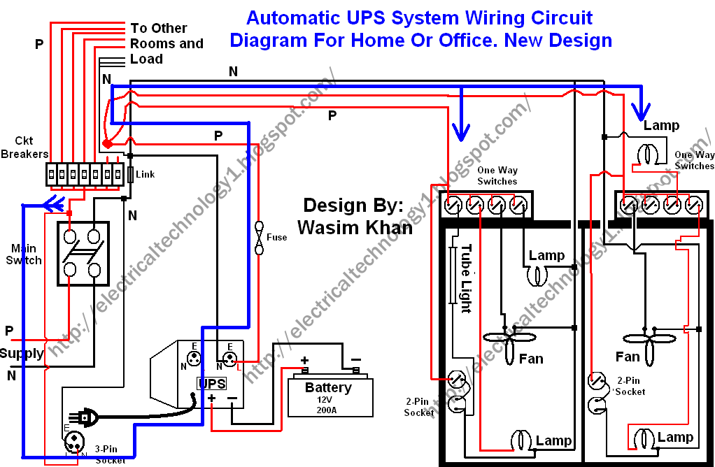
This wiring circuit diagram is designed for providing power to specific rooms in a home or office during a power supply failure. It ensures continuous power supply to devices such as laptops and computers in those particular rooms, especially...

A South African company has developed a 5-kilowatt Fuel Free Generator and discovered that the longevity of the batteries is significantly affected by the process. There are various types of batteries available for testing, including different lead-acid batteries, gel...
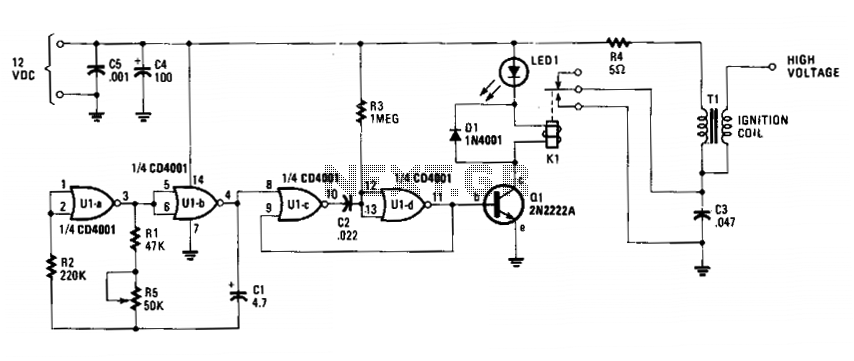
The circuit is fundamentally an auto ignition coil paired with a set of points that perform a similar function. It employs a pulsing circuit constructed from a single CMOS NOR integrated circuit (U1) to open and close relay contacts,...
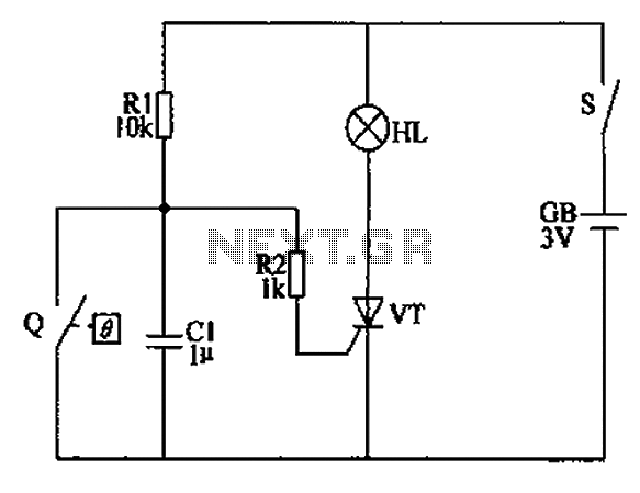
The automatic anti-frost crop controller circuit comprises an electric contact mercury thermometer (Q), a control circuit, ignition devices, and other components. The electric contact mercury thermometer features two platinum electrodes; one acts as a contact electrode inserted at the...
This text provides information about an initial attempt at creating a circuit, referencing a schematic found in an application note for a specific module. However, it notes that the schematic did not include details for the power supply circuitry,...