
Automatic UPS system wiring circuit diagram (New Design Very simple) for Home or Office
 for Home or Office")
This circuit design employs a dual-source power supply system, which is essential for maintaining uninterrupted power to critical devices. The circuit is configured to automatically switch between the main power supply and the backup system (UPS or battery) without manual intervention. The inclusion of a UPS is particularly beneficial as it not only provides backup power but also conditions the power supply, protecting sensitive electronics from voltage fluctuations.
The main components of this circuit include a circuit breaker, UPS, battery, and the necessary wiring. The circuit breaker serves as the primary safety device, disconnecting the power supply in case of overload or short circuit conditions. The UPS is connected to the main distribution board, and it should be rated appropriately to handle the combined load of the devices in the connected rooms.
Wiring connections must be executed with care, ensuring that all connections are secure and insulated to prevent short circuits. The live (phase) wires removed from the circuit breaker should be routed to the input of the UPS. The output of the UPS will then be connected to the designated rooms, ensuring that power is supplied seamlessly from the main supply when available.
In cases where the main power supply is interrupted, the UPS will automatically switch to battery power, allowing devices to remain operational without any noticeable interruption. This design is particularly advantageous for environments where continuous power is critical, such as offices with computers and other electronic equipment that cannot afford downtime.
Overall, this circuit design provides a reliable solution for ensuring that essential rooms in a building maintain power continuity, effectively combining both primary and backup power sources in a streamlined manner.This wiring circuit diagram is design for when you want to give supply to particular rooms in the home or office in the building in case of failing the power supply. And you want to supply power continuously to the laptop, computer etc in that specific rooms or office in case of low wattage UPS or single battery or in case of when generator system
is not available. . First of all, remove those Live (Phase) wires from the main distribution board (from the circuit breaker) of those particular Rooms (As shown in Fig) which you want to give automatic supply (in both cases from Battery and Power House without any interrupt or disturbance). Suppose I want to connect only these two rooms with this system as shown in fig. Then connect these two live (phase) wires at the end as shown in fig. Now do the same wiring (Connect UPS, Battery, Home appliances etc) as shown in fig. Done Then power flow will continue to those particular rooms or office at this way from Power supply (Not from Battery, because when power supply available, then battery will start to charge through UPS.
🔗 External reference
Related Circuits
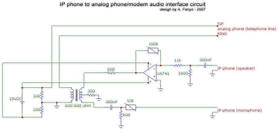
The transformer is a 600:600 ohm transformer, also referred to as a 1:1 ratio 600 ohm transformer. It has approximately the same number of turns on both the primary and secondary coils and is optimized for operation at a...

Power Amplifier Speaker Protection Circuit Schematic. When a power amplifier is switched on, a loud thump sound is often heard due to a sudden heavy discharge. The power amplifier speaker protection circuit is designed to prevent loud thump sounds during...
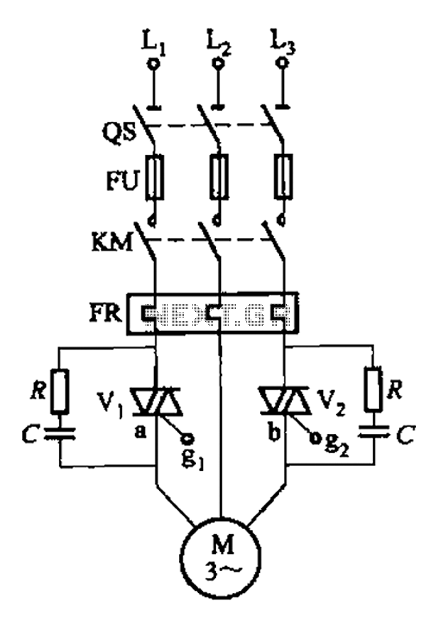
The circuit depicted in Figure 3-80 is responsible for controlling a portion of the transistor multivibrator. A multivibrator serves as a robust positive and negative feed-forward amplifier, consisting of two branches that are interconnected through a coupled RC timing...
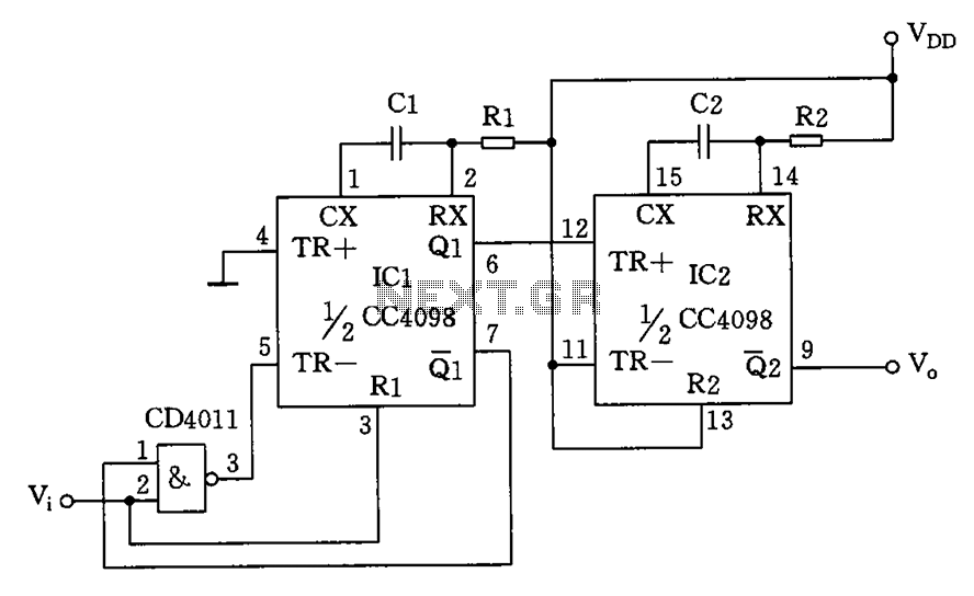
The circuit depicted features a double oscillator utilizing a monostable multivibrator CC4098 and a quad 2-input NAND gate CC4011, among other components. This circuit allows for adjustable frequency and duty cycle. It is primarily designed as a keying oscillator,...
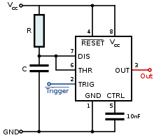
It can be assumed that most 555 timer chips from various manufacturers are interchangeable due to their similar pin configurations. However, the programs or diagrams may simplify the pin arrangements, leading to potential confusion. Custom routing may be necessary...
A simple FM transmitter connects a home entertainment system to a portable radio that can be moved around the house and into the backyard. For instance, music can be played from a CD player in the living room and...