
Automatic cycle switch circuit 2

The automatic cycle switch circuit is designed around the versatile 555 timer IC, which functions in astable mode to generate a square wave output. This output controls a bidirectional thyristor, which in turn modulates the power delivered to connected relays or loads. The circuit effectively turns the relay on and off based on the timing parameters set by the potentiometers.
The capacitive step-down circuit is implemented to ensure that the voltage applied to the 555 timer is within its operational limits, thereby enhancing its reliability and performance. The choice of a thyristor allows for efficient switching with minimal power loss, making it suitable for applications where energy efficiency is paramount.
Adjustment potentiometers RP1 and RP2 play a crucial role in fine-tuning the operation of the relay. By varying the resistance values, the timing characteristics of the relay can be altered. For example, increasing the resistance of RP1 to 300kΩ extends the pull-in time to 20 seconds, while a resistance of 220kΩ at RP2 results in a release time of 15 seconds. This flexibility makes the circuit adaptable to various operational requirements.
Overall, this automatic cycle switch circuit represents a practical solution for applications requiring controlled switching of electrical loads, with the added benefit of timing adjustments to suit specific operational needs. Automatic cycle switch circuit 2 It uses 555 IC as the control element} A capacitive step-down circuit; bidirectional thyristor V control relays or loads on and off time. RPi a djustment potentiometer and RP2 (or Cl), respectively, can be changed relay KA pull and release time. As will RPi raised 300k, 0, RPz adjusted 220kfl, the pull-in time KA 20s, the release time is 15s.
Related Circuits
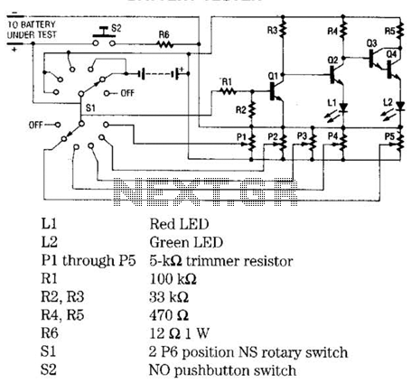
The battery tester utilizes four transistors and two LEDs to indicate the status of any battery being tested. Transistors Q3 and Q4 are configured in a Darlington arrangement, providing extremely high gain. LED L2 illuminates when a small positive...
An efficient automatic solar garden lights circuit with minimal components. The notable feature is that it operates entirely automatically, with the solar panel functioning as a light detector. The automatic solar garden lights circuit is designed to provide illumination in...
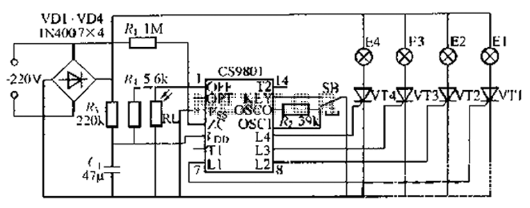
The ASIC is a flashing light string controller featuring four outputs. It includes a single key cycle control with six different lighting effects, and it allows for the selection of either 16 or 8 patterns. The circuit incorporates a...
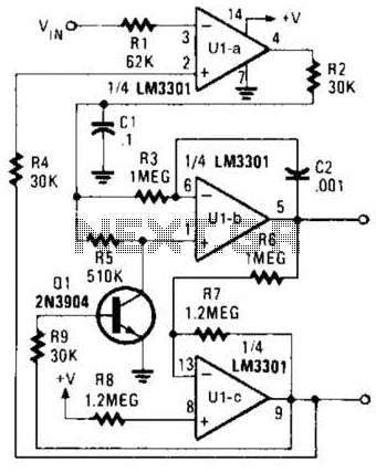
The Phase-Locked Loop (PLL) will synchronize with an input signal, providing both triangle and square wave outputs. A quad operational amplifier can be utilized in this circuit, making it suitable for audio and low-frequency radio applications. The Phase-Locked Loop (PLL)...
It is sometimes necessary to monitor a device that generates a relatively short pulse to indicate a change of status. If the duration of the input signal is too short, the RFC-1/B may not have enough time to capture...
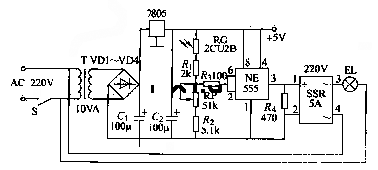
The NE555 time base circuit with an AC solid-state relay (SSR) can function as an automatic light switch circuit. The circuit diagram illustrates that during the day, the incandescent light is turned off due to the influence of the...