
Automatic emergency light circuit

The automatic emergency lighting circuit is designed to provide illumination during unexpected power outages. The primary components of this circuit include a NiCad (Nickel-Cadmium) battery, a charging circuit, a lamp, and a control mechanism that detects power failure.
When the mains power is available, the circuit allows the NiCad battery to charge, ensuring that it remains ready for use. Typically, a diode is included in the charging path to prevent reverse current flow, which could discharge the battery when mains power is restored.
In the event of a power failure, the control mechanism, often implemented with a relay or a transistor, detects the loss of voltage and subsequently activates the lamp. The lamp can be an LED or an incandescent bulb, depending on the design requirements. The circuit must be configured to ensure that the lamp operates at the correct voltage and current levels, which may involve the use of a voltage regulator or a suitable driver circuit.
The emergency lighting circuit is designed to be energy-efficient, ensuring that the battery can provide adequate illumination for a reasonable duration. The choice of a NiCad battery is significant due to its ability to deliver high discharge rates and recharge efficiently, although considerations regarding battery life and environmental impact should also be acknowledged.
Overall, this circuit serves as a practical solution for maintaining visibility during power outages, enhancing safety and convenience in residential and commercial environments.This low cost automatic emergency lighting circuit turns on a lamp during power failures. It is powered by a NiCad battery that is being charged by the mai. 🔗 External reference
Related Circuits

The NE555 timer circuit functions as a vibration generator. The input pin 3 produces pulse frequencies ranging from 5 to 20 Hz. The circuit includes a fan that operates within a bamboo enclosure. The barrel section is designed to...

The circuit utilizes the 7805 voltage regulator, which features three connections: input, output, and ground. It delivers a fixed output voltage, with the last two digits of the part number indicating the specific output voltage, such as 05, 06,...
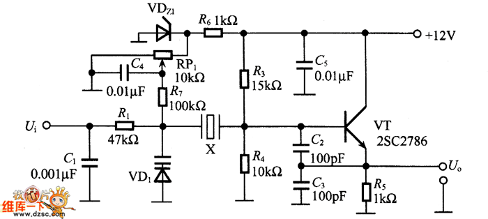
The figure illustrates the FM modulation circuit of a crystal oscillator. FM modulation can be achieved through direct and indirect methods. The direct FM method involves directly altering the frequency of the oscillating circuit. While this approach is straightforward,...

The simplicity of this transmitter, combined with its high performance, makes it particularly interesting. It has an output power of approximately 30 W, and under normal conditions, with the appropriate antenna and handling, it can achieve a range of...

An Arduino Uno is connected to two infrared (IR) transmitters and their respective receivers. When one of the receivers detects a beam break, a strand of LEDs displays a pattern. While this setup functions correctly in principle, an issue...

The core device is a circuit pyroelectric infrared sensor (BH). When it detects infrared radiation from a body, the sensor element responds to changes in temperature. As a thermoelectric element, its self-ferroelectric polarization value changes, causing a discharge of...