
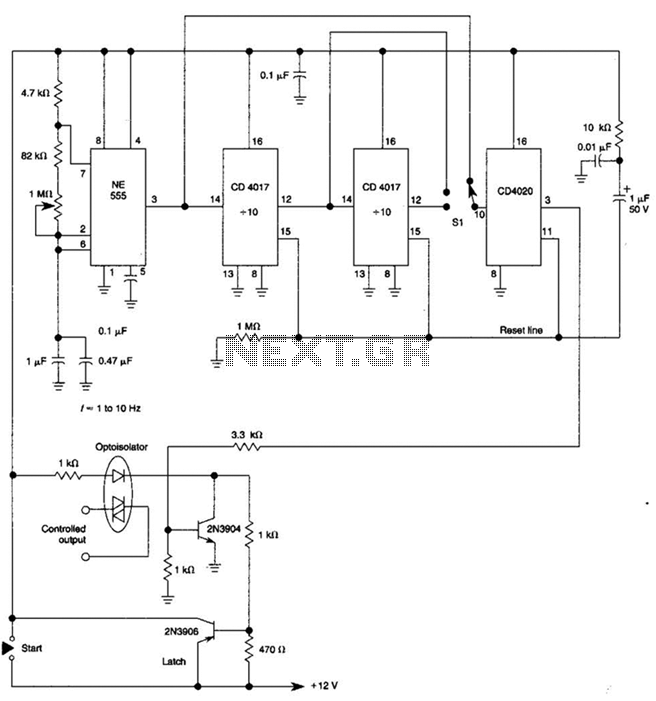
A welding load automatic power-off circuit

The NE555 timer is a versatile integrated circuit commonly used for generating precise timing and oscillation applications. In this circuit, the NE555 is configured in astable mode, which allows it to continuously oscillate between high and low states, generating a square wave output. The frequency of this oscillation is determined by the values of the resistors (R1, R2) and the capacitor (C) connected to the circuit. The output frequency can be adjusted within the range of 5 Hz to 20 Hz by changing these component values.
The circuit's output, taken from pin 3 of the NE555, is used to drive a fan located in a bamboo enclosure. The design of the barrel section allows for easy integration of the required resistors and capacitors, ensuring that the circuit can be fine-tuned for optimal performance. A transistor is incorporated into the circuit to amplify the power output, enabling the fan to operate effectively under varying load conditions.
In addition to the basic oscillation functionality, the circuit includes two operational modes. The first mode is designated for standard fan operation, while the second mode is intended for bilge selection, which may be useful in maritime applications where water removal is necessary. The "withering contingent" mode is an additional feature that stabilizes the output frequency for specific applications.
The motor speed can be controlled dynamically based on the load it experiences, allowing for efficient operation. The circuit may also include a control segment designed for compact fluorescent lights, enabling it to manage the light's operation in conjunction with the fan's function. Overall, this NE555-based circuit is a well-rounded solution for applications requiring vibration generation and motor control.NE555 tour allows just as vibration. } E input pin 3 River) pulse frequency ult / 5 ~ 20Hz Fan Cave weeks bamboo. Barrel section to ridicule steep scheduled for R and C. Value. m transistor 1j and T} Hungary throw success rate system level power output fl1 sail. AJl and f can control the oscillation frequency of 555. There are "Shai fans" and "shift" models t bilge selection. "Withered contingent" mode is set f rinse certain frequency. Juice motor drawing to determine the speed. "Change" Bu marrow type the compact fluorescent Sichuan F1 motion control segment continued Ba f f Section vmiiJ pupil Cui motor speed.
Related Circuits
By using three 555 ICs, three sequential pulses can be generated. Output 3 can be connected back to the trigger input to achieve astable operation. The circuit described utilizes three 555 timer integrated circuits (ICs) configured to generate three sequential...
This device, available in a Stainless DIL 8 package, is capable of measuring four independent analog voltages ranging from 0 to 5 volts. It transmits the measurement results as four characters via a standard asynchronous serial link. The described device...

A CMOS logic gate is utilized in this circuit. When an object approaches the antenna, the change in oscillator output is detected by components 1)1 and 1)2, which is then amplified by U1C. This amplification drives Q1, activating alarm...
An advantage of a photogate over a sound trigger is that the former activates based on the exact position of the object that interrupts the beam. For instance, the shape of a snapped elastic cord can be captured as...
The AM transmitter circuit consists of an audio amplifier and an RF oscillator. The oscillator is constructed around transistor Q1 and its associated components. The tank circuit, which includes inductor L1 and variable capacitor VC1, is tunable from approximately...
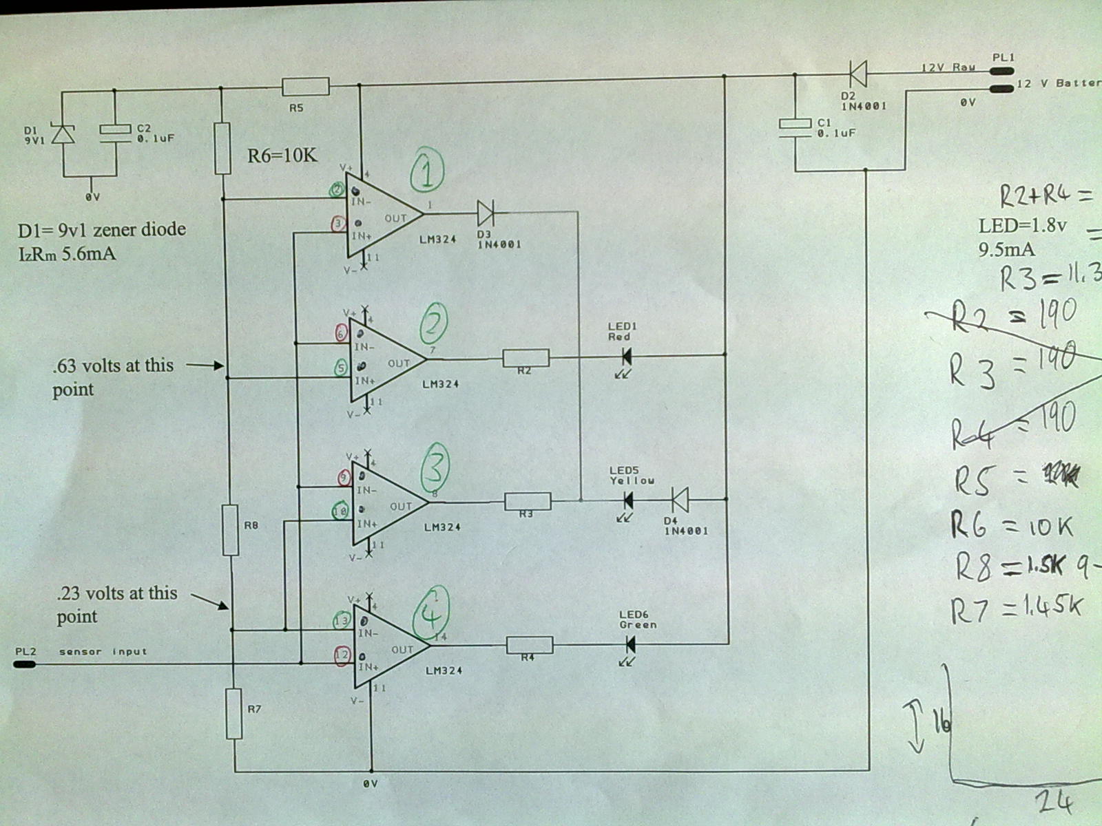
A 12V power supply is connected to the positive terminal, allowing current to flow through a protection diode and a capacitor that smooths the voltage. A zener resistor (R5) limits the current to the zener diode, which regulates the...