
Simple Valve MW Transmitter circuit 30W

This transmitter circuit is designed for effective radio frequency (RF) transmission, characterized by its simplicity and robust performance. The PL 84 oscillator plays a crucial role in generating the RF signal, which is essential for the operation of the transmitter. The oscillator's output is fed into the L1 coil, which serves as a resonant circuit to enhance the signal strength before it is transmitted.
Coil L1, specifically designed for the 6SA7 lamp, ensures that the oscillation frequency aligns with the desired transmission frequency, optimizing the transmitter's efficiency. The RFC1, with its specified inductance of 2.5 mH, acts as a radio frequency choke, allowing DC to pass while blocking RF signals, thus preventing interference in the power supply line.
The output stage of the transmitter is powered by the PL 509 lamp, which is known for its ability to handle high power levels, thus contributing to the overall output power of approximately 30 W. The L2 coil, constructed with 50 turns of enamel wire, is essential for further signal amplification and stabilization, ensuring that the transmitted signal maintains its integrity over longer distances.
The variable capacitors C1 and C2 are integral to tuning the transmitter, allowing for fine adjustments to the resonant frequency of the circuit. This capability is vital for ensuring that the transmitter can operate effectively across a range of frequencies, accommodating various audio sources.
Transformer T1, with its primary winding featuring a 2.5K resistor, is designed to step up the voltage to the required levels for efficient transmission. The power rating of 6 W indicates that it is well-suited for the transmitter's operational requirements without overheating or failing.
The diode D is included in the design to rectify the signal, capable of handling up to 700 mA at 250 V, ensuring that the transmitter operates safely and reliably under various conditions. The modulator input, which can be excited by a crystal microphone or other audio sources, allows for versatile audio input options, making the transmitter suitable for a range of applications in communication systems.The simplicity of this transmitter compared to its very high performance makes it very interesting. Its output power is about 30 W and its range under normal conditions, with proper antenna and handling, reaches 30 km. The oscillator is the PL 84 which provides enough signal to normally excite the output light. Coil L1 is the oscillation coil of the 6SA7 lamp. The RFC1 has a 2.5mH inductance and can operate at a current of 100mA. The PL 509 power lamp is used in the output stage.
The L2 coil consists of 50 coils of 1 mm thick enamel wire, wound into a 5 cm diameter drum. RFC2 has an inductance of 29mH and can operate at 600mA.
The variable capacitors C1 and C2 have a capacity of 500 pF each, with thin sheets. Transformer T1 has a primary with a 2.5K resistor. Its power is 6W. Diode D operates at 250V and can withstand 700mA current. The input of the modulator is excited by a crystalline microphone or by any other audio source.
Related Circuits

The robot requires a method for detecting obstacles (or other robots) without making physical contact. This capability allows the robot to determine whether to avoid or confront and investigate the obstacle based on its programming. This document outlines the...
An LED, or Light Emitting Diode, is a semiconductor device that allows current to flow in one direction while blocking it in the opposite direction. This characteristic makes LEDs polarized components, having a positive side known as the anode...
1. A robot may not injure a human being or, through inaction, allow a human being to come to harm. 2. A robot must obey the orders given to it by human beings, except where such orders would conflict...
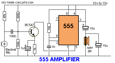
The 555 timer can function as an amplifier, operating similarly to pulse-width modulation. The component values lead the 555 to oscillate at approximately 66 kHz, a frequency to which the speaker does not respond. Instead, the speaker reacts to...
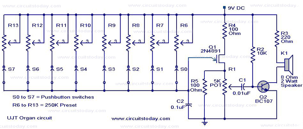
A UJT organ circuit with a circuit diagram is explained in detail. A 2N4891 UJT is used for the operation of the circuit. The UJT (Uni-Junction Transistor) organ circuit is designed to utilize the unique characteristics of the 2N4891 UJT...
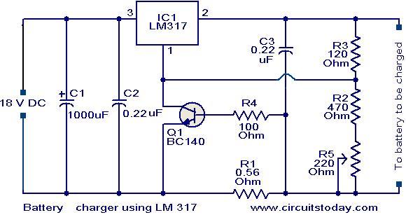
This is a simple yet effective battery charger circuit utilizing the LM317 integrated circuit (IC). The circuit is designed for charging 12V lead-acid batteries and can be easily assembled on a general-purpose printed circuit board (PCB). The core component...