
Automatic Heat Detector
The circuit is designed to leverage the thermal sensitivity of the complementary transistor pair, where the BC109 npn transistor is typically more responsive to temperature increases compared to its pnp counterpart, the AC188. The operation principle relies on the fact that both transistors will exhibit changes in their current flow as the temperature varies, allowing for effective heat detection.
In the circuit layout, the BC109 is configured in such a way that it amplifies the signal generated by temperature changes, while the AC188 can be used to switch or control a load based on the output from the BC109. The configuration may include resistors to set the biasing conditions for both transistors, ensuring optimal operation within their specified ranges.
The output of this circuit can be connected to an indicator, such as an LED, or can be integrated into a more complex system where heat detection is critical, such as in temperature monitoring systems or safety devices that shut down equipment in the event of overheating.
Overall, this complementary transistor circuit is a robust solution for heat detection applications, providing a reliable method for monitoring temperature changes through the use of semiconductor technology.This circuit uses a complementary pair comprising npn metallic transistor T1 (BC109) and pnp germanium transistor T2 (AC188) to detect heat (due to outbre.. 🔗 External reference
Related Circuits

Metal detectors can be categorized based on their operational principles into three types: BFO (Beat Frequency Oscillator), TR/IB (Transmit-Induction/Balance), and PI (Pulsed Induction). Each method has its own set of advantages and disadvantages. An ideal metal detector, which does...
The LED phototransistor light gate should be mounted approximately 1 to 2 cm apart, within a rigid housing. It was mounted on a brass piece attached to the circuit board. The housing must accommodate the compass without obstructing the...
LED 1 will light and the buzzer turns on when the coil is changing inductance. The setup is easy, VR1 is adjusted (away from any metal objects) so that LED 1 will light and the buzzer sounds on, and...
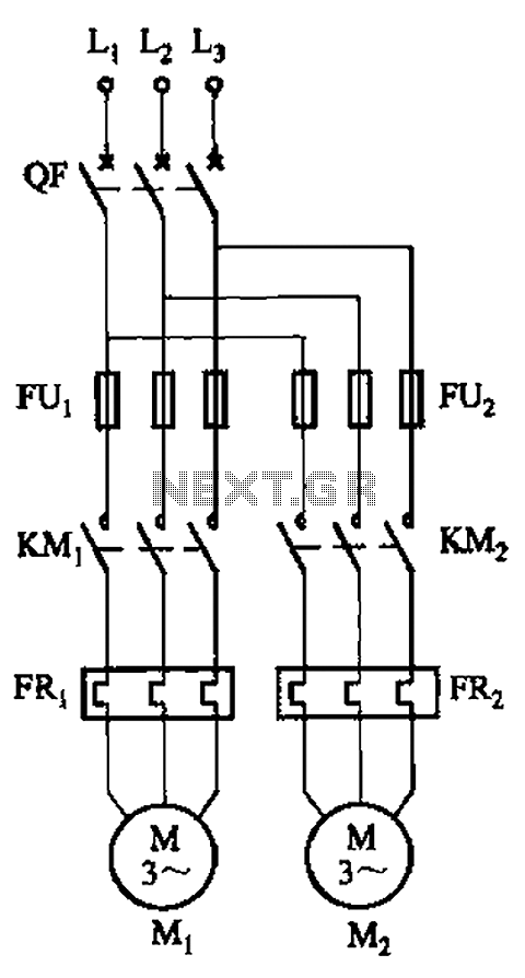
The circuit illustrated in Figure 3-64 operates with switch SA1 in the work position and switch SA2 in the standby position, allowing motor Mi to run while motor Mz remains on standby. In the event of downtime for motor...
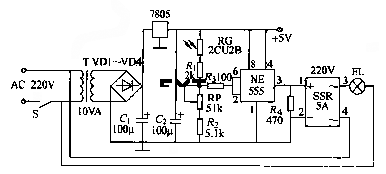
The NE555 time base circuit with an AC solid-state relay (SSR) can function as an automatic light switch circuit. The circuit diagram illustrates that during the day, the incandescent light is turned off due to the influence of the...

An automatic battery charger initiates the charging process when the battery voltage falls below a specified threshold and ceases charging once the voltage exceeds a predetermined maximum value. The setup is straightforward; simply connect two alligator clips to the...
Warning: include(partials/cookie-banner.php): Failed to open stream: Permission denied in /var/www/html/nextgr/view-circuit.php on line 713
Warning: include(): Failed opening 'partials/cookie-banner.php' for inclusion (include_path='.:/usr/share/php') in /var/www/html/nextgr/view-circuit.php on line 713