
Compass Detector

t up. The coil we have suggested is actually two coils and we used them set up in parallel to work with each other (the diagonally opposite legs should be connected together), which is why there are two in the diagram. In the circuit we used (and the diagram above) the collector of the phototransistor was connected to the zero rail, and the emitter was connected to pin 2 of the op-amp.
If your circuit does not work, try switching the legs over. When the circuit is built and double checked, then test the output of it (pin 6), it should be around (plus or minus) 10 volts or higher when there is nothing blocking the light, but drop to near zero volts when the path is blocked. Now you are ready for a test. Align the coil and the compass, so that the needle will block the light gate when it pointing East-West.
The coil should be about half a centimetre from the end of the needle to start with. Now switch on the circuit, and the compass should swing round towards the coil a little. If this does not happen the chances are that the coil`s magnetic field is parallel to that of the compass, to rectify this you can turn the coil around, or switch the terminals of the coil, or turn the whole detector around. Once the coil is making the needle rotate a little way you need to insert the soft iron into the coil, very slowly.
The needle should come further round until it is in the beam, where it should sit. If you do this too fast the needle will be able to come through the beam, and you will probably have to start the moving of the soft iron all over again. If you are monitoring the voltage of the output you will notice that the further in the coil the iron goes the nearer to zero the output gets (unless the needle leaves the beam all together).
Assuming that you are setting the detector up on a magnetically quiet day then you will want the output voltage to be somewhere near the middle of the output range. You might want to note this voltage for later. This should be performed away from natural light as this upsets the detector, and makes it too unstable to set up.
Once the needle has been caught and you switch off you should be able to use a weakly magnetic object (e. g. , a screwdriver) to place the needle back in the light gate when you turn it back on (remember to have the same end of the needle in the gate as when you set it up).
No further adjustment of the soft iron should be needed. As the overall light levels can affect the output of the circuit it is better to have the circuit in a box (not a metal box). Other things to watch out for are to not have the power supply or leads passing to close the the compass, and to have you measuring device a reasonable distance from the compass (1 metre or so should be fine).
Please note that if for some reason the output of the op-amp does not go to zero when the light is blocked, but instead changes from positive to negative (or vice versa), then the needle will not come to rest, and you should try and make sure that this does not happen, but it will probably only be down to having the phototransistor in the wrong way around, or something reasonably simple. How you take readings is up to you, as what you are measuring is just a voltage. Some systems can measure very small changes over large ranges, and these are great, but for those who don`t have this advantage you will want to provide a reference voltage much closer to the output that you measured when you set up the detector.
This means that instead of having to measure changes of hundredths of volts on a meter range of ten volts, you can measure them on a range of one for instance. A 4. 7MOhm potentiometer (variable resistor) across the 15V of the power supply should do the trick. The second two will run happily by themselves for long periods of time. The first will have to be monitored in much the same way as the pop-bottle detector, once an hour until the movements become larger when more frequent reading should be taken.
If absolute results are to be compared (not very advisable) then you must ensure that all things stay the same, reference voltage for the measuring device, position of soft iron piece, and positions of nearby large metal objects. However as long as the device is set up in a similar way for each period of measurement it is acceptable to compare relative results (i.
e. , not actual voltages, but voltage changes). The values suggested will work, but actual outputs may vary due to component tolerances. When taking readings it is important that the detector is as far from moving metal objects as possible as they will disturb it. This includes busy roads, railways, and lifts (elevators). The results page will give some idea of what might be expected from your detector. 🔗 External reference
Related Circuits
The GLMDPCB motion detector board is a double-sided etched, screened, and drilled printed circuit board designed for the GLMDA motion detector circuit illustrated in the schematic below. The circuit can be constructed in its entirety or in part. For...
This project involves a simple dark detector LED circuit. In a previous discussion, a light-activated LED circuit was presented. By rearranging the positions of the resistors and the Light Dependent Resistor (LDR), the circuit has been transformed into a...
The detector circuit compares the output voltage of two separate voltage dividers with a fixed reference voltage. The resultant absolute error signal is amplified and converted to a logic signal that is TTL compatible. The described detector circuit serves as...
This electronic schematic allows for the design of a simple cellular phone detector circuit capable of sensing the presence of an activated mobile phone from a distance of 1.5 meters. The capacitor C3 should have lead lengths of 18...
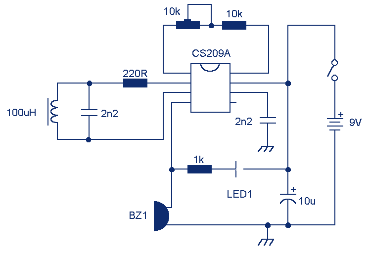
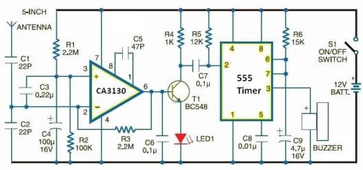
LED 1 will light and the buzzer turns on when the coil is changing inductance. The setup is easy, VR1 is adjusted (away from any metal objects) so that LED 1 will light and the buzzer sounds on, and...
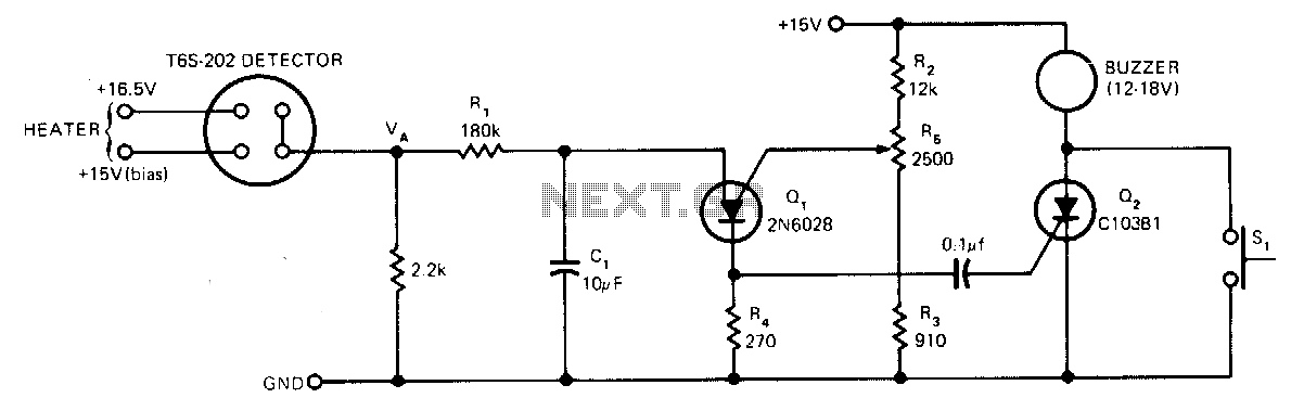
The sensor operates based on the selective absorption of hydrocarbons by an n-type metal-oxide surface. The device features a heater designed to eliminate hydrocarbons once smoke or gas is no longer detected in the immediate vicinity, allowing for reuse....