
Automatic Lamp Dimmer Circuit

This automatic light dimmer circuit employs a combination of passive and active components to achieve a gradual transition in lighting intensity. The primary components include a switch (S1), a capacitor (C1), a transistor (T1), a light-emitting diode (LED), a light-dependent resistor (LDR), a silicon-controlled rectifier (SCR), and a potentiometer (P2).
Upon closure of switch S1, capacitor C1 begins to charge through a resistor, which dictates the charging time constant. The gradual increase in voltage across C1 is critical, as it determines when T1 will start conducting. The threshold voltage of 0.6 volts is a characteristic of the transistor, allowing it to enter the active region and drive the LED.
The brightness of the LED is directly proportional to the current flowing through T1, which is regulated by the voltage across C1. As the LDR detects ambient light levels, its resistance decreases when the LED is illuminated, thereby influencing the SCR's conduction. This feedback loop creates a smooth increase in brightness as the circuit responds to the changing conditions.
When S1 is opened, the discharge path for C1 through T1 is slow, allowing for a gradual reduction in current, thus dimming the LED smoothly. This feature is essential in applications where abrupt changes in lighting can be undesirable, such as in home theater systems or ambient lighting setups.
The adjustment of potentiometer P2 is crucial for setting the desired anode voltage of diode D1. This voltage adjustment ensures that the circuit remains in a stable state during standby, preventing any flickering or unintended activation of the lighting system when it is not in use. The design of this circuit exemplifies the integration of electronic components to achieve a user-friendly and aesthetically pleasing lighting solution.This automatic light dimmer circuit makes it possible to control a lighting system so that it turns on or off slowly. The circuit works this way: when switch S1 is closed, the capacitor C1 is slowly charged. Once the voltage at C1 reaches 0. 6, transistor T1 begins to conduct and the LED also begins to light. If the capacitor voltage increases furt her, then transistor T1 conducts more current and in return the LED lights brighter. If the LED lights up, the LDR resistance decreases causing the SCR to conduct periodically earlier. This tehnique causes the lighting system to turn on slowly. On the other hand if switch S1 is turned off, meaning the switch is opened, the LED does not immediately turn off since the capacitor voltage at the base of T1 discharges slowly. The LED slowly dims until finally turns off. This causes the lighting dim out before it finally turns off. Potentiometer P2 must be set so that the anode voltage of D1 is about 0. 7 volts. If this is done, the capacitor voltage will be around 0. 5 volts during standby, meaning lights off. 🔗 External reference
Related Circuits
The schematic in question is unconventional in design and should not be used as a model for beginners in electronics. A significant drawback of this basic circuit is that the alarm is triggered only when the light beam on...
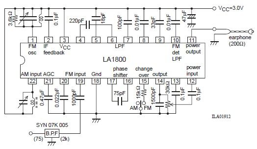
This portable AM/FM radio circuit is designed using the LA1800 integrated circuit (IC) along with several external components. The LA1800, manufactured by Sanyo Semiconductors, requires only a few additional components for its operation. The output signal is directed to...
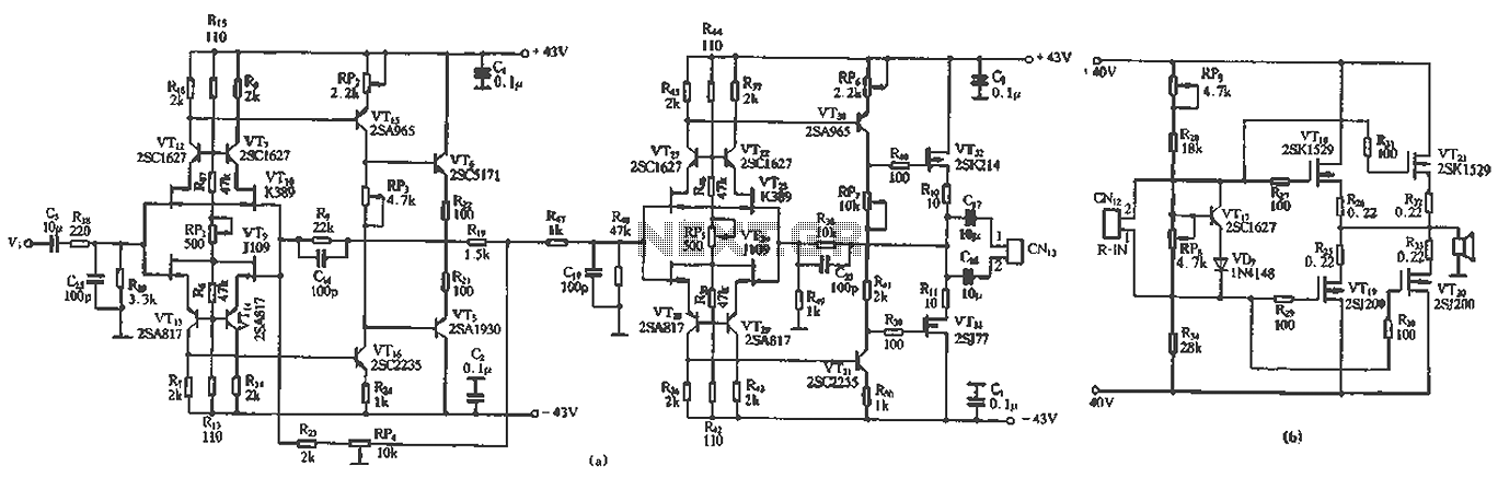
The circuit design features a unique technology and a reasonable structure utilizing all-discrete components with a Class A FET output. The complete circuit includes an input stage, an output stage, and a power level circuit to enhance performance, along...
Just point this small device at the TV and the remote gets jammed. The circuit is self-explanatory. 555 is wired as an astable multivibrator for a frequency of nearly 38 kHz. This is the frequency at which most of...
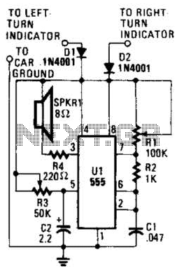
This circuit is designed to assist individuals with hearing impairments by generating a tone each time a dashboard turn indicator is activated. The frequency of the tone decreases for the duration that the indicator remains lit. The circuit operates by...
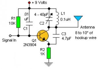
Experimenting with the size of the coil and the number of turns can influence the frequency and signal output of the oscillator. The signal can be received using a standard FM radio receiver. The input signal should be coupled...