
la1800 portable am fm radio circuit

The portable AM/FM radio circuit utilizing the LA1800 IC is a compact and efficient design suitable for personal audio applications. The LA1800 is a highly integrated radio receiver IC that simplifies the design process by incorporating essential functions such as frequency selection, demodulation, and audio amplification within a single package.
The circuit typically includes a few passive components, such as resistors and capacitors, which are used to set the gain and filter the audio output. An antenna is also required for signal reception, which can be a simple wire or a more sophisticated telescopic antenna, depending on the desired range and reception quality.
For the output stage, the circuit is designed to drive earphone speakers directly. In scenarios where higher audio output is necessary, an external small power audio amplifier can be added. This amplifier should be compatible with the output level of the LA1800 to prevent distortion and ensure optimal performance. The connection to the amplifier usually involves routing the audio output from the LA1800 to the input of the amplifier, which then drives the larger speaker.
Overall, this circuit design is ideal for hobbyists and engineers looking to create a portable radio solution with minimal components while maintaining high audio quality and functionality.This portable am fm radio circuit is designed using the LA1800 IC and some other external components. As you can see in this circuit diagram the LA1800 manufactured by Sanyo Semiconductors, require few additional components.
Also the output signal is driven into earphone speakers, but you can use an additional speaker ( in that case you need t o connect an additional small power audio amplifier ). 🔗 External reference
Related Circuits

The thermostat electric circuit operates as depicted in the figure. It has three settings: off, low power (Lo), and high power (Peru HL). When the DIP switch SA is set to the Lo position, 220V AC is directed through...
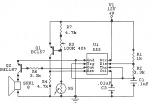
The following circuit illustrates a Sun Up Alarm Light Alarm Circuit Diagram. This circuit is based on the 555 Integrated Circuit (IC). Features include simplicity and cost-effectiveness. The Sun Up Alarm Light Alarm Circuit employs the 555 timer IC in...
The Accu charger circuit is straightforward and simple to construct, requiring no more than ten components. In addition to its ease of assembly, this charger circuit is also cost-effective and highly efficient. The circuit requires a power supply from...
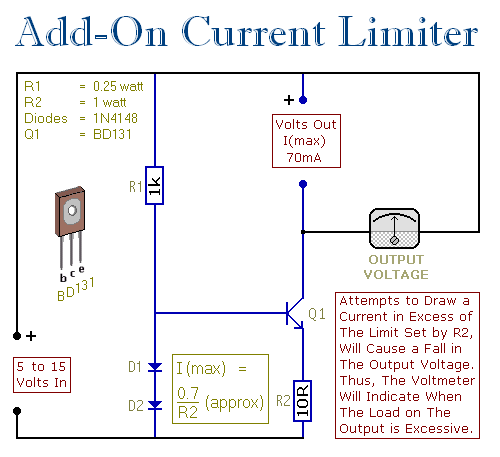
This circuit allows setting a limit on the maximum output current from a power supply unit (PSU). It is particularly useful when powering up a project for the first time or conducting a soak test. By establishing an upper...
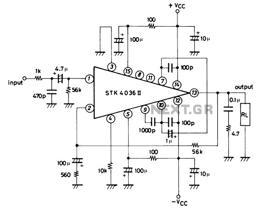
This is a 50-watt audio power amplifier circuit based on the single IC STK4036II. A heatsink is required to prevent overheating of the IC. The amplifier circuit provides good sound quality at an affordable price and is easy to...
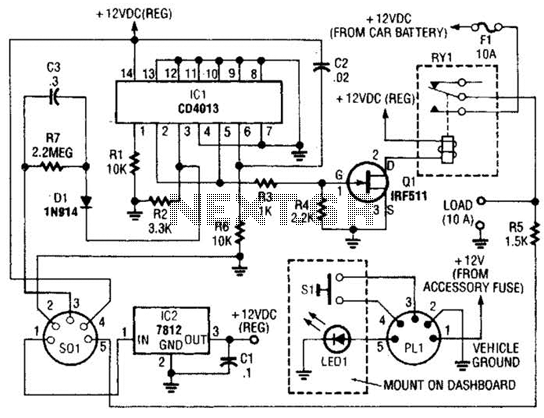
The power controller operates from the vehicle's accessory switch, allowing the load to receive power only when the ignition key is in the "on" position. A momentary pushbutton controls a load of up to 10 A using half of...