
Automatic Lawn Light with LDR

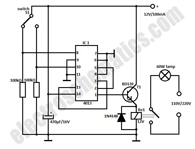
The described circuit functions as an automatic control system for garden lighting, specifically designed for incandescent bulbs. It utilizes solid-state components to ensure reliability and efficiency. The key components of this circuit typically include a light-dependent resistor (LDR), a transistor, and a relay or a solid-state switch.
The LDR is employed to detect ambient light levels. During daylight, the resistance of the LDR is low, preventing the circuit from activating the light bulbs. As the sun sets and ambient light decreases, the resistance of the LDR increases, triggering the transistor. The transistor acts as a switch, allowing current to flow through the relay or solid-state switch, which in turn activates the connected incandescent garden light bulbs.
The circuit may also incorporate additional features such as a potentiometer to adjust the sensitivity of the LDR, allowing the user to set the threshold at which the lights will turn on. Furthermore, a diode may be included to protect against back EMF generated by the relay when it is deactivated, ensuring the longevity of the components.
Overall, this automatic lawn light circuit provides an efficient solution for garden illumination, enhancing both aesthetics and safety during nighttime hours. Its solid-state design minimizes maintenance requirements while ensuring consistent performance.Circuit of a compact and true solid-state automatic lawn light is described here. The circuit can be used to switch on incandescent garden light bulbs at. 🔗 External reference
Related Circuits
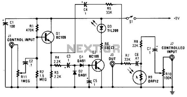
In this circuit, audio input to the control channel is amplified and rectified by diodes D1 and D2. This direct current level activates LED D3 through transistor Q2. The illumination from LED D3 causes R9, a light-dependent resistor, to...
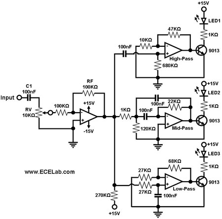
Figure 1 illustrates a simple circuit designed for converting an audio signal (such as one from the output terminals of a CD player). The circuit primarily consists of a buffer/amplifier stage and three filtering circuits: a high-pass filter, a...
A compact and intriguing circuit designed to flash automotive headlights. It utilizes a well-known NE555 timer circuit to achieve this functionality. The circuit operates by employing the NE555 timer in astable mode, which allows it to generate a continuous square...
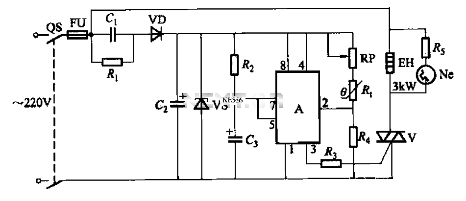
An automatic temperature control circuit is designed for climate control thermostats. Its primary function is to maintain a constant internal temperature using an electric heater (EH). The control mechanism utilizes a negative temperature coefficient thermistor as the temperature sensing...
This automatic door light switch circuit activates a lamp when a door is opened and deactivates it when the door is closed again. The working principle of the circuit involves a sensor that detects the door's position. The automatic door...
This robot was designed as a project for secondary school pupils to build during an activity day. The chassis was provided to the pupils pre-cut. The total cost of the components per robot was just under GBP 5, including...