
Light Dark Sensor With Relay Circuit Using LM741

The schematic has been enhanced by incorporating a 220µF smoothing capacitor between the base of transistor Q1 and ground. This addition effectively mitigated relay chatter, which occurred when the relay rapidly switched on and off at the light level threshold. The inclusion of the capacitor completely resolved the issue of relay chatter.
According to the circuit designer, the relay will be activated only when no light is detected by LDR1. However, testing has shown that users can adjust the potentiometer (P1) to set the relay closure at any desired light level. By swapping the positions of the 10K resistor (R1) and the LDR (LDR1), the relay will engage when the LDR is exposed to light, allowing for automatic device shutdown during nighttime.
Since the circuit utilizes a relay, modifications are necessary to reduce power consumption, making it more suitable for low-current applications powered by renewable energy sources.
The LM741 light/dark sensor circuit operates by using a light-dependent resistor (LDR) to detect ambient light levels. The LDR's resistance decreases with increasing light intensity, which alters the voltage at the non-inverting input of the LM741 operational amplifier. This change is compared to a reference voltage set by the potentiometer (P1), allowing for user-defined sensitivity.
When ambient light falls below a certain threshold, the output of the LM741 transitions, turning on the NPN transistor (Q1). This transistor, in turn, activates the relay, allowing current to flow through the connected load. The relay serves as an electrically operated switch, controlling larger currents and voltages safely, isolating the low-power control circuit from the high-power load.
The addition of the 220µF smoothing capacitor at the transistor's base is crucial for stabilizing the input signal. It filters out high-frequency noise and prevents rapid on-off cycling of the relay, which can lead to wear and tear, as well as erratic operation. This modification enhances the reliability of the circuit, particularly in environments where light levels may fluctuate rapidly.
For applications requiring operation under renewable energy conditions, such as solar power, it is essential to consider the overall power draw of the circuit. This may involve selecting a relay with lower coil current requirements or utilizing solid-state relays (SSRs) that can be triggered by lower control voltages and currents. Additionally, optimizing the component values, such as using a higher resistance for R1 or a more sensitive LDR, can further reduce power consumption while maintaining functionality.
Overall, this LM741 light/dark sensor circuit provides a versatile solution for automated lighting control, with the flexibility to adapt to various light conditions and power requirements.Above is a schematic diagram of an LM741 light/dark sensor circuit (from the excellent 741 Op-Amp Tutorial by Tony van Roon).The ECG128/NTE128 transistor stipulated can be substituted with any NPN transistor rated at sufficient gain and current for the chosen relay coil. We have modified the schematic diagram above with the addition of a 220uF smoothing capacitor between the base of transistor Q1 and ground.
Without this capacitor, the relay chatter (relay switching on and off many times per second) was terrible around the switch on/off light level. By adding the capacitor, relay chatter was completely eliminated. According to the designer of this circuit, the relay will be closed only when "NO light falls on LDR1", however, in testing this circuit proved to work very well with the user able to adjust the potentiometer (P1) to automatically close the relay at whatever light level they chose. By swapping the postitions of the 10K resistor (R1) and the LDR (LDR1), the relay will be closed when the LDR is under light rather than under darkness.
Therefore a device can automatically be switched off at nighttime. Since this circuit still contains a relay we need to make some changes* to reduce the amount of power to make it more suitable for renewable energy powered low-current applications. 🔗 External reference
Related Circuits
This schematic represents an FM transmitter capable of delivering an output power of 3 to 3.5 W, operating within a frequency range of 90 to 110 MHz. While the stability of the circuit is acceptable, the integration of a...
It is advisable to prototype the entire circuit using a breadboard. This method simplifies the process significantly compared to attempting to determine the connections on a small printed circuit board. Prototyping a circuit on a breadboard allows for easy modifications...
Engineer Radu Preda from Romania has developed two energy-saving lighting circuits designed to control the duration that lights are activated, ultimately aiming to reduce electricity expenses. The first circuit utilizes a relay, while the second employs an optoisolator triac...
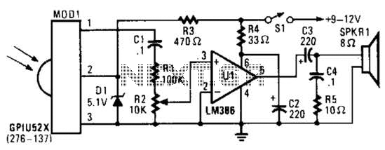
This circuit utilizes an infrared pulse-to-audio converter to assist in troubleshooting infrared remote controls, making it an effective tool for detecting infrared light sources. It employs a photo cell module (Radio Shack P/N 276-137) to detect IR radiation and...
The device being constructed will serve as a metal detector, capable of locating metal objects such as coins, nails, and keys, including car keys that may be misplaced. It can also detect gold, although it may not possess industrial...
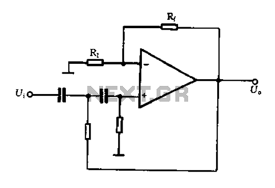
A typical two high-pass filter circuit. A high-pass filter (HPF) is an electronic circuit that allows signals with a frequency higher than a certain cutoff frequency to pass through while attenuating signals with frequencies lower than the cutoff frequency. A...